Permanent magnet motor

a permanent magnet, magnet motor technology, applied in the direction of dynamo-electric brake control, mechanical energy handling, propulsion system, etc., can solve the problem that magnet motors still require external power sources

Inactive Publication Date: 2005-03-15
FECERA FR J
View PDF50 Cites 65 Cited by
  • Summary
  • Abstract
  • Description
  • Claims
  • Application Information

AI Technical Summary

Problems solved by technology

However, these conventional permanent magnet motors still require a source of external power to produce a rotating magnetic field.

Method used


Image

  • Permanent magnet motor
  • Permanent magnet motor
  • Permanent magnet motor

Examples


first embodiment

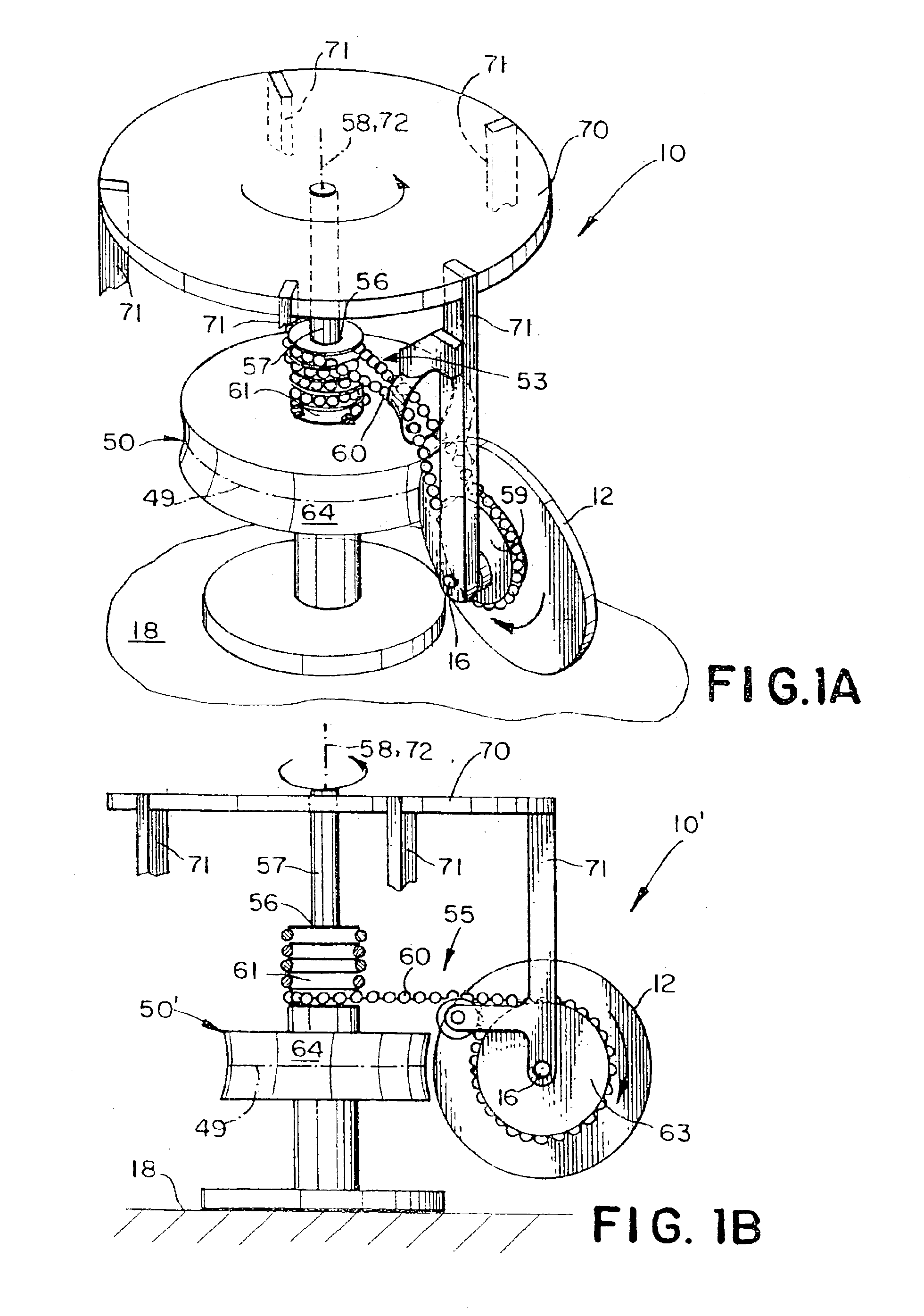
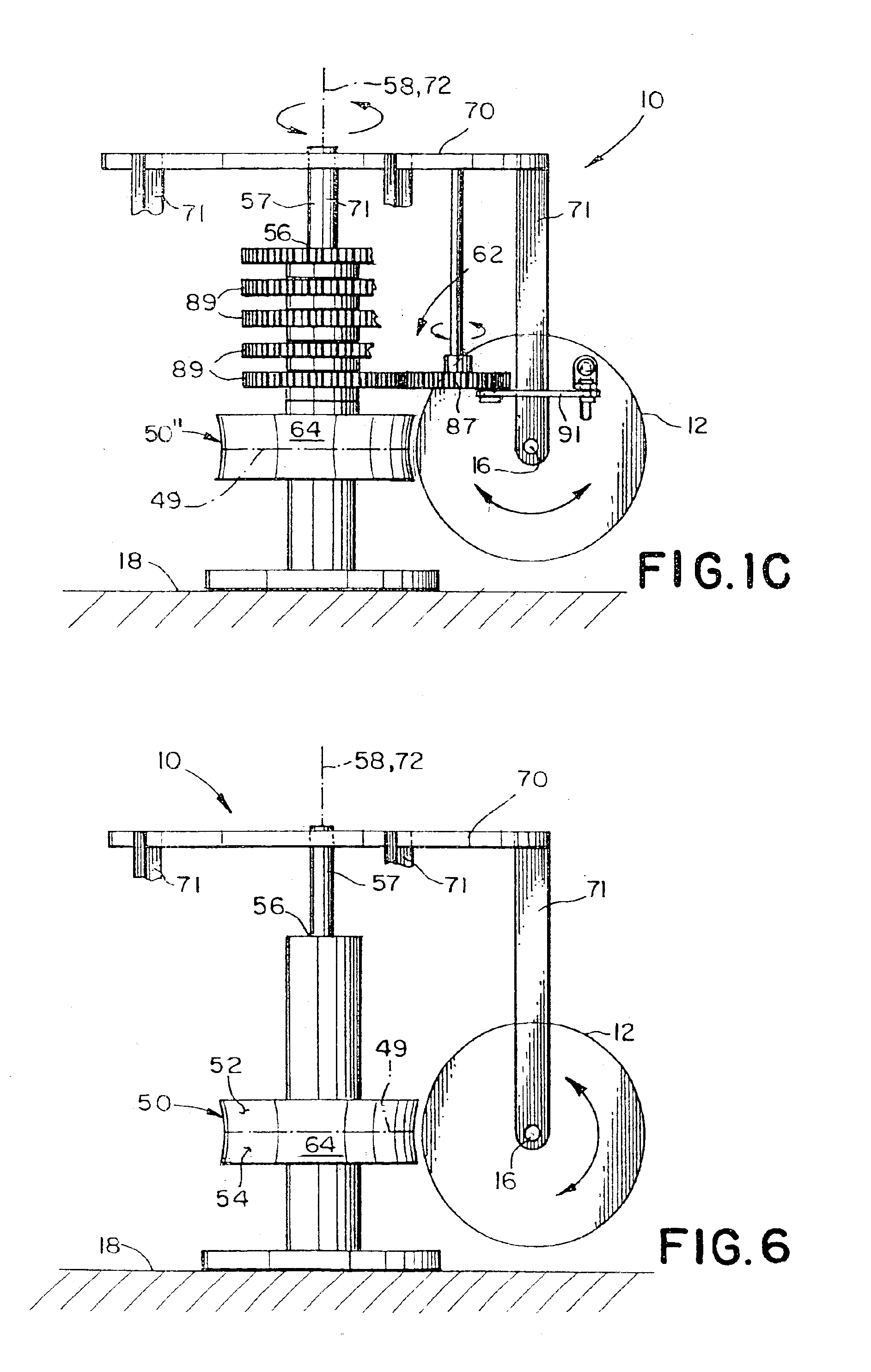
Referring now to FIGS. 1A, 2 and 3 there is shown a first preferred embodiment of a motor 10 using the rotor 12 and providing unidirectional rotational motive power. The first preferred embodiment comprises a generally circular stator 50 having a stator axis 72 and a circumferential surface 64 mounted to a base 18; an armature 70, having an armature axis of rotation 58 coincident with the stator axis 72, attached to the stator 50 by an armature axle 57 for rotation about the armature axis of rotation 58; and five rotors 12 (only one of which is shown for clarity), the rotors 12 being spaced at intervals of about 72 degrees around the armature 70. Each rotor 12 is spaced from the armature by an armature strut 71 and attached to the armature strut 71 by an axle, for rotation about an axis 16 of the rotor 12 in a plane generally aligned with the armature axis of rotation 58. The motor 10 further includes a linkage assembly 53 drivingly connecting each rotor 12 and the stator 50 togethe...

fourth embodiment

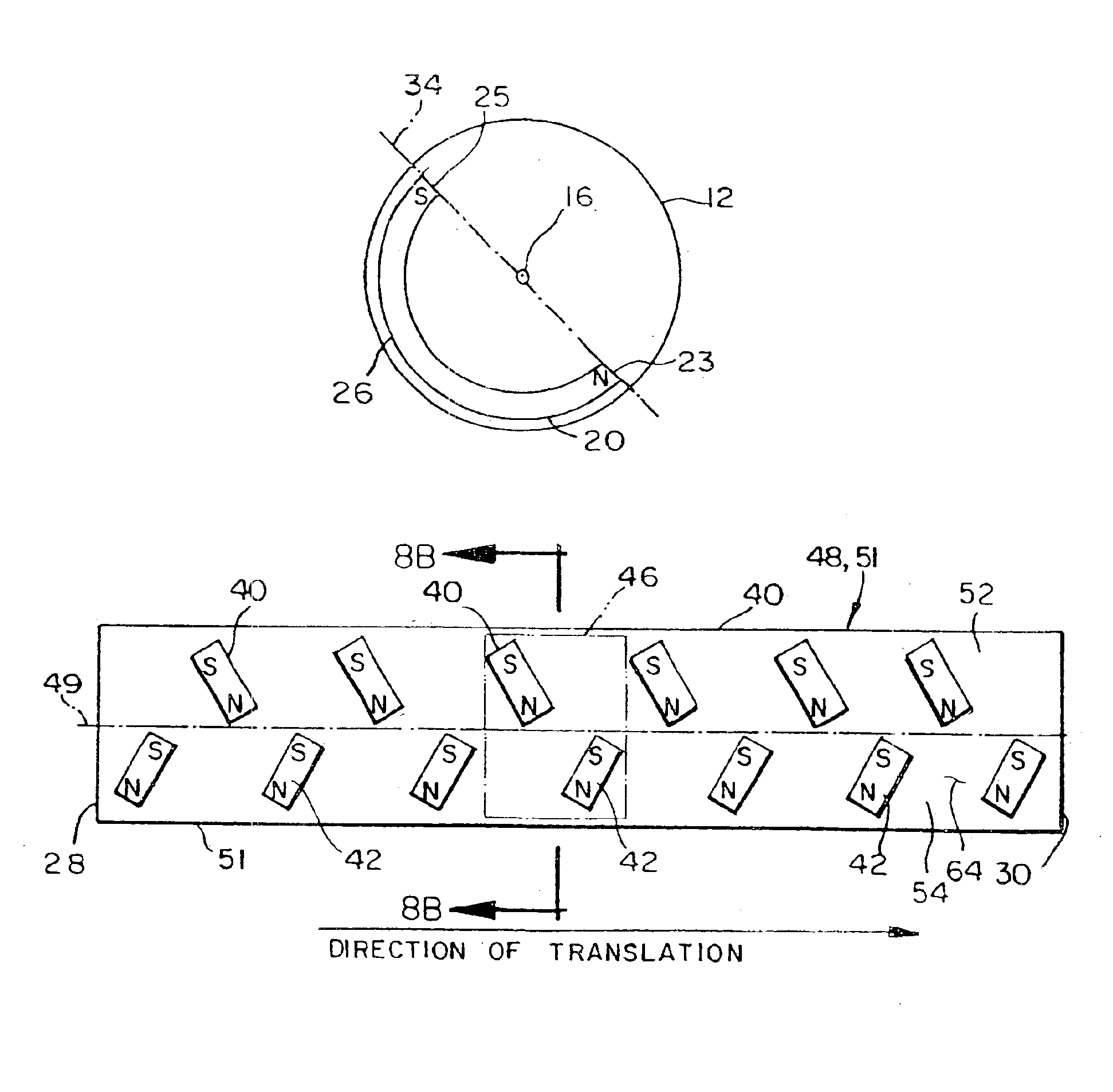
Referring now to FIG. 7A, each rotor 12 comprises a first U-shaped magnet 20 generating a second magnetic field. The first U-shaped magnet 20 is positioned on the rotor 12 such that the north pole and the south pole of the first U-shaped magnet 20 faces toward the axis 16 of the rotor 12, and the rear side 26 of the first U-shaped magnet 20 faces the periphery of the rotor 12. When the rear 26 of the first U-shaped magnet 20 is adjacent to the north pole of one of the first stator magnets 40 along the line of demarcation 49, a portion of the second magnetic field directly adjacent to the rear 26 of the first U-shaped magnet 20 interacts with a portion of the first magnetic field generated by the north pole of the first stator magnet 40 to cause the rotor 12 to rotate in a counterclockwise direction. As the rotor 12 rotates in the counterclockwise direction, a portion of the second magnetic field associated with the south pole of the first U-shaped magnet 20 interacts with a portion ...

fifth embodiment

Referring now to FIGS. 6 and 8C-8D there is shown a sixth preferred embodiment of the motor 10. The structure and operation of the sixth preferred embodiment is identical to that of the fifth preferred embodiment except that: (1) the stator magnets 40′, 42′ on the surface 64 of the stator 51′ are in a slightly different orientation; (2) an additional stator magnet 41 is added to each pair of stator magnets 46 and (3) the U-shaped magnets 22, 24 attached to each rotor 12 are replaced with bar magnets 36, 38: Specifically, and referring now to FIG. 8C, the direction of magnetization of each first stator magnet 40′ and each second stator magnet 42′ is aligned to be generally perpendicular to the line of demarcation 49 instead of being inclined in the pre-determined direction around the armature axis of rotation 58 as in the Also, the stator 51′ also includes a third stator magnet 41 mounted on the outer surface 64 along the line of demarcation 49 midway between each first stator magne...


PUM


Abstract

A motor providing unidirectional rotational motive power is provided. The motor has a generally circular stator with a stator axis, an outer surface, and a circumferential line of demarcation at about a midpoint of the outer surface. The motor also includes one or more stator magnets attached to the outer surface of the stator. The stator magnets are arranged in a generally circular arrangement about the stator axis and generate a first magnetic field. An armature is attached to the stator for rotation therewith, the armature having an axis parallel to the stator axis. One or more rotors, are spaced from the armature and coupled thereto by an axle for rotation about an axis of each rotor, each rotor rotating in a plane generally aligned with the armature axis. Each rotor includes one or more rotor magnets, with each rotor magnet generating a second magnetic field. The second magnetic field generated by each rotor magnet interacts with the first magnetic field to cause each rotor to rotate about the rotor axis. A linkage assembly drivingly connects each rotor to the stator to cause the armature to rotate about the armature axis thereby providing the unidirectional rotational motive power of the motor.

Description

BACKGROUND OF THE INVENTIONThis invention relates to dynamo electric motor structures and more particularly to rotary and linear permanent magnet motors.Conventional electric motors rely on the interaction of magnetic fields to produce a force which results either rotary or linear motion. The magnetic fields in conventional electric motors providing rotary power are generated by passing an externally provided electric current through conductors in either a stator (i.e. stationary portion of the motor), a rotor (i.e. rotary portion) or both the stator and the rotor. The rotary power of the motor arises from a rotating magnetic field which is created by commutating the electric current, either by a switching the current through different conductors, as in a direct current motor or by a polarity reversal of the electric current as in an alternating current motor.It is well known that a class of materials known as ferromagnetic materials are also capable of generating a magnetic field h...

Claims


Application Information

Patent Timeline
Patent Type & Authority Patents(United States)
IPC IPC(8): H02K53/00
CPCH02K53/00
Inventor FECERA, FRANK J.
Owner FECERA FR J
Why Eureka
Try Eureka