Low-Cost Minimal-Loss Flywheel Battery

a flywheel battery and low-cost technology, applied in the field of rotary kinetic energy storage and retrieval mechanisms, can solve the problems of low drag loss at acceptable levels, inconsistent locations with flywheel safety, and only short duration power of the flywheel storage device, so as to minimize the radial thrust of the ball bearing, no viscous drag nor vacuum enclosure contamination, and low-cost minimal loss

Inactive Publication Date: 2010-11-11
FRADELLA RICHARD B
View PDF100 Cites 60 Cited by
  • Summary
  • Abstract
  • Description
  • Claims
  • Application Information

AI Technical Summary

Benefits of technology

[0037]A flywheel assembly having magnetically levitated vertical-spin-axis rotor support, including axially magnetized ring magnets juxtaposed to repel each other, which provide stable upward axial force, to support the rotor weight without need for electric power, and can accommodate moderate earthquakes; plus ceramic ball bearings near the top and bottom of the rotor, to maintain rotor centering, including consistent axial preload that augments rotor lift forces, is described herein and shown in FIG. 1, for a low-cost minimal-loss flywheel battery system. The present invention sets forth new configurations of ceramic ball bearings with lubricant coating, and thus almost no viscous drag nor vacuum enclosure contamination due to oil or grease lubricant evaporation. It also sets forth design details to provide consistent axial preload, and minimize ball bearing radial thrust from slight but inevitable rotor unbalance and precession torque due to Earth rotation. Said design details are intended to maximize ball bearing service life and minimize bearing rolling friction power losses.
[0038]Applicant's present invention also includes minimal-loss attributes provided by flywheel assembly magnetic materials adjoining said ceramic ball bearings, because they are not magnetically cycled. It further includes new minimal-loss high-reliability electronics. The present invention also sets forth flywheel assembly self-leveling means, for electric power storage and regeneration with minimal losses, which can tolerate moderate earthquakes and ground level shifting without performance or reliability degradation over the long service lifetime intended.
[0039]A safe, cost-competitive, minimal-loss, zero-maintenance flywheel battery for providing long duration power and having a long service life would provide significant benefits over high-power-loss flywheel storage that provides only short duration power, chemical battery storage, and fuel-burning generators, or combinations of chemical battery and flywheel battery storage to start fuel-burning generators used in stationary sites.
[0040]Accordingly, the present invention seeks to provide lower-cost flywheel batteries, for stationary installations, affording very long and reliable service life with zero maintenance, and additionally incurring far lower energy losses than other prior art flywheel power storage devices. It also seeks to facilitate practical on-site distributed solar and wind power installations.

Problems solved by technology

Most of these flywheel storage devices provide only short duration power due to their high continuous losses.
These locations are generally not consistent with flywheel safety.
Vacuum loss in prior art flywheel enclosures, due to flywheel assembly parts outgassing, may necessitate an integral vacuum pump, or costly maintenance, to keep air drag loss at acceptably low levels.
That usually precludes their installation in a site that can safely absorb the energy released if the flywheel rotor disintegrates while spinning at high speed.
Viscous friction in mechanical bearings that need lubrication can cause considerable drag torque at high spin speeds, and vacuum loss due to lubricant evaporation.
Mechanical bearings of some prior art would incur serious heating and wear, running in vacuum at sustained high speed.
Also, very high operating temperatures of critical bearing parts have been caused by heat generated from bearing losses, compounded by low heat transfer, further compounded by bearing lubrication loss accelerated by lubricant boil-off in vacuum.
Prior art ball bearing applications have resulted in early bearing wear, their subsequent deterioration, and high failure rates.
Prior art flywheel teachings do not include design considerations to mitigate precession torque due to Earth rotation (which tends to tilt the rotor assembly and therefore adds to rotor bearing radial loads).
All types require frequent maintenance, may fail without warning, and deteriorate over time.
Their lifetimes are usually limited to less than ten years—far shorter if subjected to repeated frequent deep charge and discharge cycles or not promptly recharged after supplying power.
Most have toxic waste disposal problems.
These battery drawbacks have been a major obstacle to on-site solar and wind power installations, because power storage, especially for off-grid installations, is subjected to daily charge and discharge cycles.
Wind power is sporadic, and imposes additional power storage charge and discharge demands.
Said prior patents do not teach spring means to apply a consistent ball bearing inner race lift force, which provides both a stable rotor lift force plus a consistent axial preload for the two ball bearings spaced a maximum practical axial distance from each other.
Said prior patents do not address means to mitigate radial loads to ball bearings caused by Earth rotation precession torque which acts on a spinning flywheel rotor assembly.
Said patent also does not teach means to mitigate problems from level shifting and from precession torque due to Earth rotation.
Its many attributes are very useful, but achieving them is difficult and requires very exacting conditions.
However, it needs critical rotor balance and vibration damping means, to prevent damage to its ceramic ball bearings by rotor vibration, major earthquakes, and extreme shaking.
Additionally, ground loops (signal interference caused by small fractions of high electromagnet actuator currents in signal grounds) are troublesome.
Moreover, although only minimal power for the prototype flywheel rotor's magnetic bearing servos will be needed during steady-state operation, peak power demand for said servos at startup or while limit-cycling can exceed 1000 watts.
Radial and axial control must be simultaneously activated, because axial control alone is susceptible to rotor tilt instability; as predicted by analysis and witnessed during tests.
Also, flywheel assembly tasks are relatively complex for said prior flywheel battery, and unless crucial precautions are heeded, can be hazardous to assemblers, working with magnetic forces up to a few hundred pounds between parts, caused by permanent magnets in the assembly.
Assembly procedures are very difficult, involving such high force requirements and high stray fields, combined with very small, sensitive and delicate sensors.
Therefore, labor and tooling cost is also considerably higher, for flywheel batteries taught in applicant's prior patents.

Method used


Image

  • Low-Cost Minimal-Loss Flywheel Battery
  • Low-Cost Minimal-Loss Flywheel Battery
  • Low-Cost Minimal-Loss Flywheel Battery

Examples


Embodiment Construction

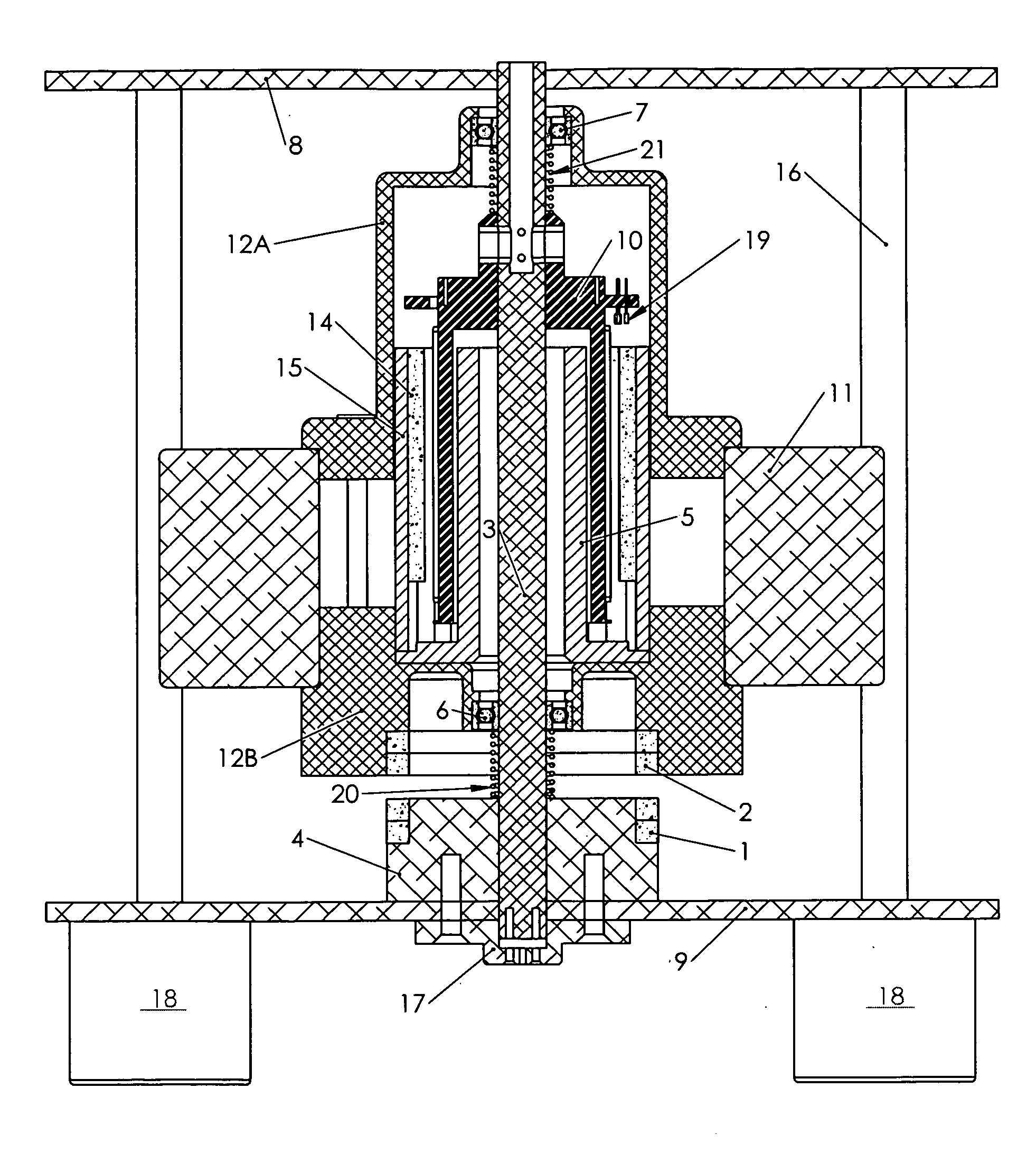
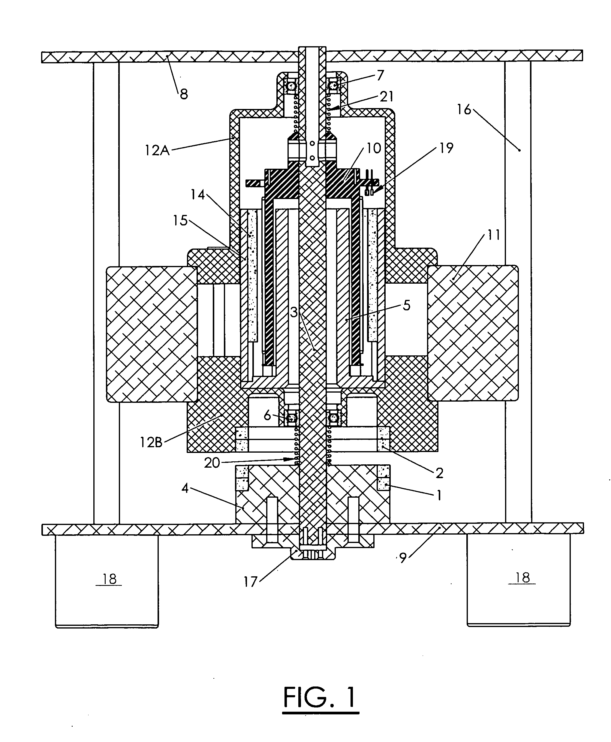
[0074]A flywheel battery system is herein described, for storing and regenerating on-site electric power for a DC power bus in a stationary installation, by way of reference to FIG. 1, followed by detailed descriptions of its component elements and general variations. This system converts electric power to stored kinetic energy by the system's regenerative motor (sometimes referred to as a motor / generator because it alternately serves as a motor when accelerating the flywheel rotor and as a generator when decelerating the rotor).

[0075]FIG. 1 illustrates a cross-sectional view of a preferred embodiment of the flywheel assembly according to this invention; comprising axially magnetized ring magnet 1 affixed radially and axially relative to center shaft 3 by stator magnet holder 4; and like magnet 2, oriented to repel magnet 1. Magnet 1 and magnet 2 were each constituted by axial 2-magnet stacks, so that off-the-shelf magnets could be used for prototype quantity flywheel assemblies. FI...


PUM


Abstract

A low-cost minimal-loss zero-maintenance flywheel battery, to store electric power from a DC power source by conversion to kinetic energy, and regenerate electric power as needed. Its vertical spin-axis rotor assembly is supported axially by repelling annular permanent magnets, and is centered by ceramic ball bearings which have axial preload that prevents vibration and augments axial rotor support. A regenerative multi-pole permanent-magnet motor, controlled by its 2-phase stator current, and connected by power and signal conductors to power interface electronics, is integrated within the flywheel assembly, in a vacuum enclosure supported by a self-leveling structure. Sinusoidal 2-phase stator currents are controlled by high-frequency pulse-width-modulated H-bridge power electronics that draw and regenerate controlled DC current with minimal ripple, responsive to respective 2-phase rotation angle sensors, the DC power voltage, and other settings. The electronics includes logic and over-voltage protection to prevent otherwise possible damaging current and voltage.

Description

CROSS REFERENCE TO RELATED APPLICATIONS[0001]The contents of the co-pending application filed simultaneous herewith having docket number ExcEn_RPM_Regen entitled “Broad-Speed-Range Generator” and invented by the present inventor is incorporated herein by reference in entirety.BACKGROUND OF THE INVENTION[0002]1. Field of the Invention[0003]This invention pertains generally to rotary kinetic energy storage and retrieval mechanisms, and more particularly to flywheel batteries for converting electric power and storing it as kinetic energy, and regenerating electric power on demand.[0004]Specifically it sets forth flywheel assemblies having a vertical spin axis supported axially by passive magnetic bearings, stabilized radially by ceramic ball bearings, cooperative with an integral regenerative motor controlled by power interface electronics, to provide practical long-duration electrical energy storage and regeneration, with minimal energy losses.[0005]2. Description of the Related Art[0...

Claims


Application Information

Patent Timeline
Patent Type & Authority Applications(United States)
IPC IPC(8): H02K7/02H02K7/09
CPCY02E60/16H02K7/025F16C39/066F16C19/166F16C25/083F16C2361/55
Inventor FRADELLA, RICHARD B.
Owner FRADELLA RICHARD B
Why Eureka
Try Eureka