
Compensation of sonar image data primarily for seabed classification

a sonar image and seabed technology, applied in the field of seabed classification compensation, can solve the problems of not offering a method or methodology for determining the sediment type, not offering a proposal for generating processed data that would adequately, and not always correcting the angle of incidence precisely for both spreading loss and absorption of sound by water, etc., to enhance the processing of echo amplitudes, enhance the image of the seabed, and improve the identification of shipwrecks

Inactive Publication Date: 2005-03-15
QUESTER TANGENT CORPORATION
View PDF9 Cites 12 Cited by
  • Summary
  • Abstract
  • Description
  • Claims
  • Application Information

AI Technical Summary

Benefits of technology

Although the present invention is particularly useful for and is described principally in the context of sediment classification, the compensation technique according to the invention has wider application. For example, the invention can also enhance images of the seabed for the improved identification of shipwrecks or aircraft debris. In principle, the invention can be used to enhance the processing of echo amplitudes from any exposed stratum or object capable of providing an echo amplitude from the reflection or backscattering of a transmitted sonar pulse.

Problems solved by technology

TVG does not always correct precisely for both spreading loss and absorption of sound by water.
Further, TVG does not adjust for the angle of incidence at all.
This is inappropriate for sediment classification as it makes the recorded backscatter from a sediment type dependent on adjacent areas and the survey direction.
This research offers some insight into the classification problem but does not offer a means or methodology for determining the sediment type, nor any proposal for generating processed data that would adequately represent seabed classification by sediment type or otherwise.
However, such a technique does not have the advantages of statistical approaches, which are intuitive and give useful results with a wide range of sonar systems that do not have to be calibrated.

Method used


Image

  • Compensation of sonar image data primarily for seabed classification
  • Compensation of sonar image data primarily for seabed classification
  • Compensation of sonar image data primarily for seabed classification

Examples


Embodiment Construction

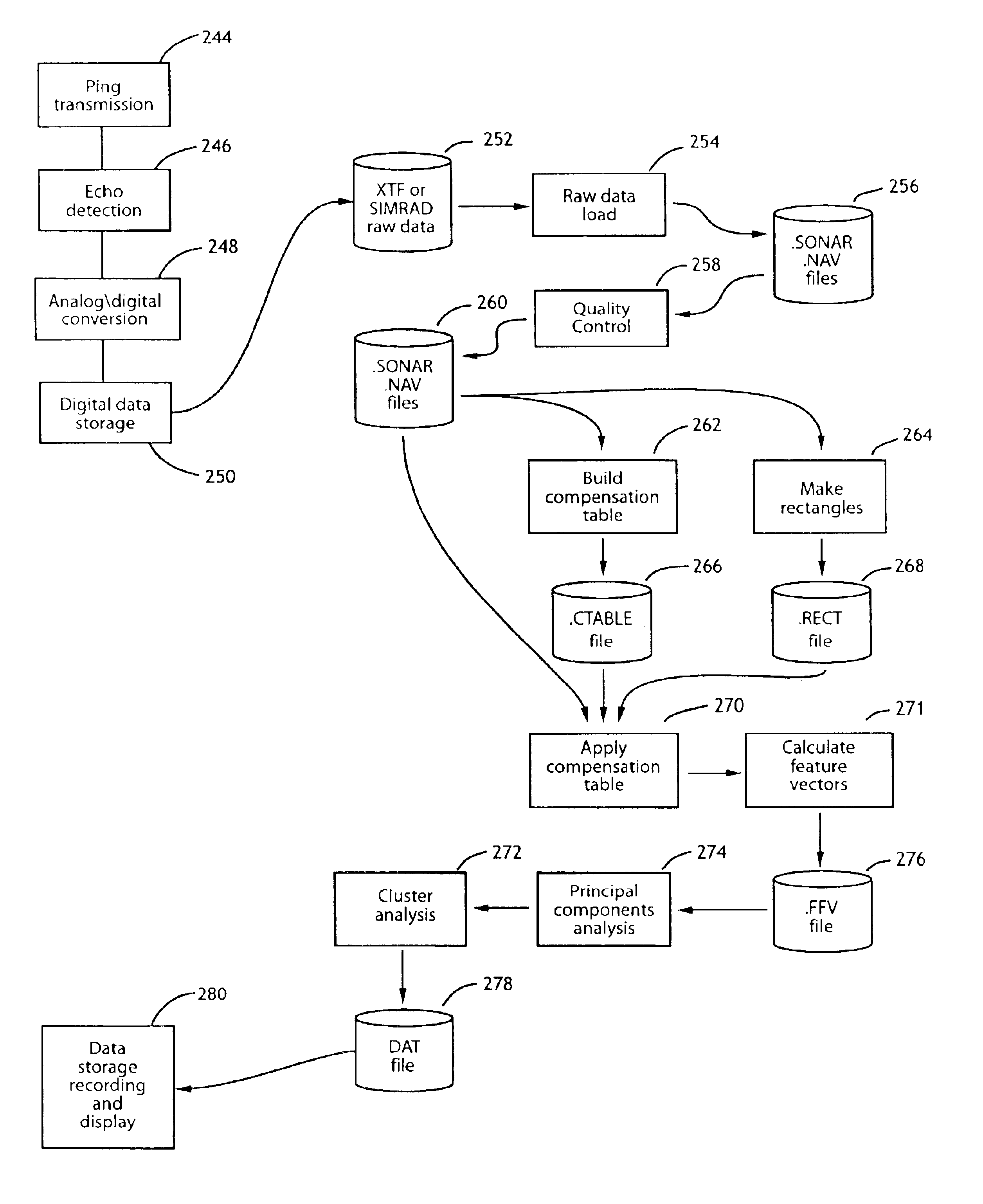
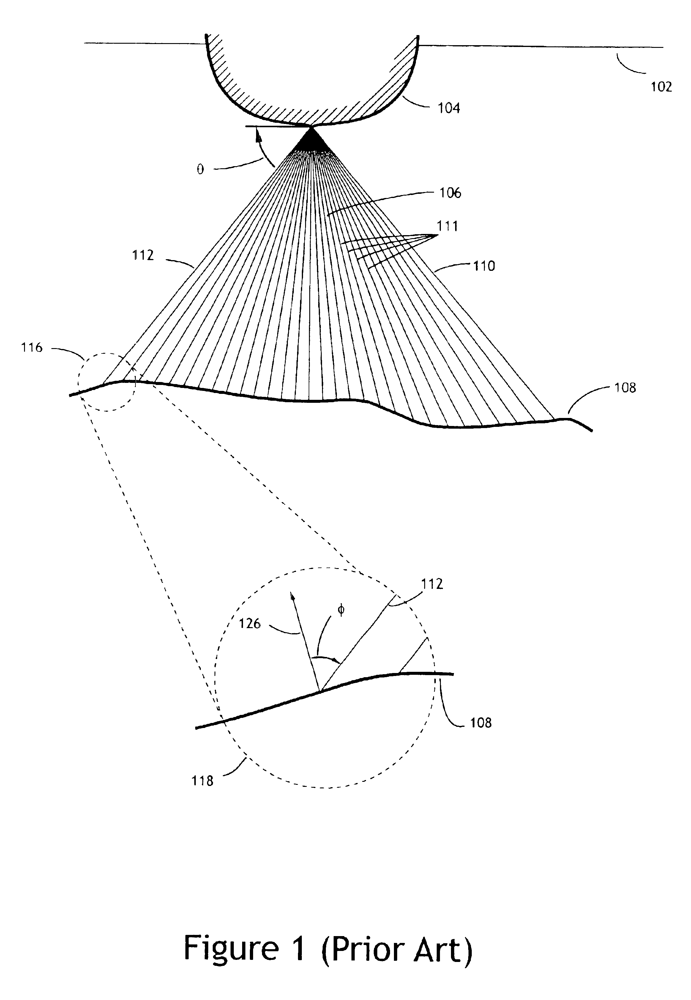
FIG. 1 shows schematically a cross-section athwartships of a vessel 104, travelling in a direction into the plane of FIG. 1 and emitting a repeated series of pings from a transmitter (not shown) located in the vicinity of the keel of the vessel 104. Each ping is made up of a short pulse of sound waves that propagate approximately spherically out towards the seabed 108. The surrounding water level is shown as 102.

The transmitter transmits a ping lasting typically between 0.2 and 15 ms. To avoid interference between successive pings, it is not possible to transmit a second ping until the echo from a first ping has returned to the vessel 104. In water of a depth requiring a sound wave to traverse a range of 250 metres, the round-trip time is approximately one third of a second. Typically, soundings are made twice per second.

A detector (not shown), including complementary sampling and data-processing equipment, is located in the vicinity of the transmitter. The analog signals of sound e...


PUM


Abstract

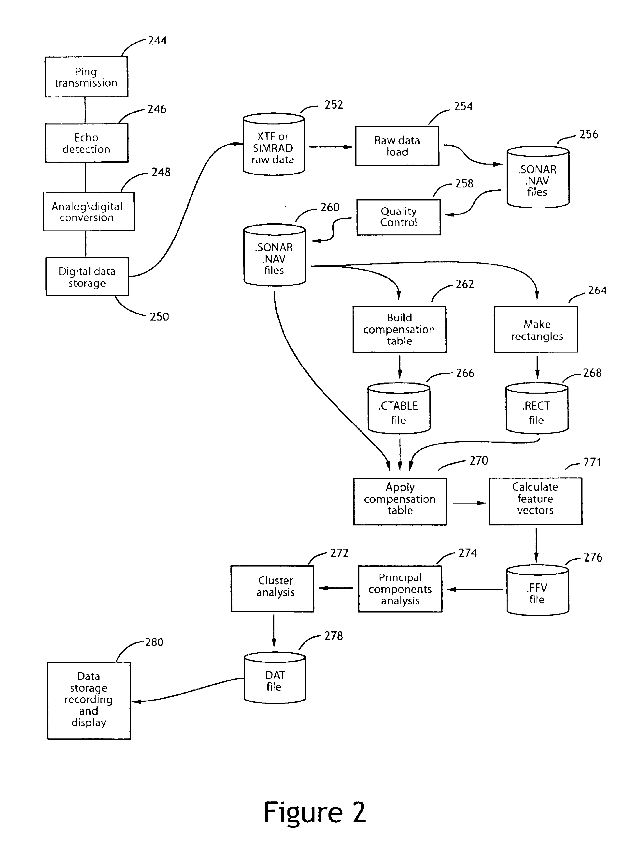
The composition of the seabed can be estimated by measuring the amplitude of echoes back-scattered from the seabed. However, the amplitude measured varies not only with the type of material present on the seabed but also with the range travelled to and the angle of incidence of the transmitted pulse at the seabed. This invention is a method for adjusting the amplitudes of backscattered echoes to compensate for the attenuation due to range and angle of incidence. A compensation table is created, each cell of which is associated with a unique combination of a partition of range and a partition of angle of incidence values. Each cell contains summary data for all echo amplitudes associated with that cell. The echo amplitude values are then adjusted using the summary data held in the compensation table.

Description

FIELD OF THE INVENTIONThis invention relates to a technique for estimating the characteristics of the seabed from the amplitudes of echoes received from sound waves transmitted at the seabed. More particularly the invention specifies a method for compensating the amplitudes received from multibeam and sidescan sounders by removing the effects of range and angle of incidence thus providing improved classifications of seabed characteristics such as sediment composition.BACKGROUND OF THE INVENTIONThe estimation of seabed characteristics is made using multibeam and sidescan sounders. Typical of the sounding equipment used is that supplied by the Norwegian company Kongsberg Simrad. For example, the EM 1002 echo sounder records echoes over a 3.3° wide arc (measured fore to aft) and over a 150° sector (measured athwartships) at 95 kHz. For shallow water operations, a pulse of duration 0.2 ms is used and the amplitude of the backscattered echo is sampled at a suitable selected frequency in ...

Claims


Application Information

Patent Timeline
IPC IPC(8): G01S7/539G01S7/52G01V1/38G01S15/89G01S15/00
CPCG01S7/52004G01S7/539G01S7/52003G01V1/38G01S15/89
Inventor PRESTON, JONATHAN M.CHRISTNEY, ANTHONY C.
Owner QUESTER TANGENT CORPORATION
Learn More