Roller assembly for supporting a slide-out room

a technology for rolling parts and sliding rooms, which is applied in the direction of shafts and bearings, mechanical equipment, building roofs, etc., can solve the problems of damage to the floor of the main living quarters

Inactive Publication Date: 2005-03-22
GARDNER STEWART
View PDF2 Cites 16 Cited by
  • Summary
  • Abstract
  • Description
  • Claims
  • Application Information

AI Technical Summary

Benefits of technology

According to the present invention, a cylindrical roller assembly including a frame and a roller carrier on which a cylindrical roller is mounted is mounted on the frame via an adjustable connection to adjust the position of the roller relative to the frame. The roller carrier articulates with respect to the frame so that the roller can move relative both to the floor of the slide-out room and to the floor of the main living quarters as the slide-out room is extended and retracted. The roller is covered by a semi-rigid material that will not mark or otherwise damage the floor as the slide-out room is extended and retracted. Because of the articulating connection between the roller carrier and the frame, the roller can flex slightly relative to the floor of the main living quarters to accommodate any vibration, bumps or similar road shocks during transportation. Accordingly, the roller will not damage the floor as often occurs in prior art slide-out rooms in which the slide-out room is supported through a rigid connection. In such prior art arrangements, damage the floor of the main living quarters may result, particularly if the floor is a tile floor or a similar easily damaged material. The roller thus is also able to accommodate movement between carpeted and tiled sections of the floor when the slide-out room is extended and retracted.

Problems solved by technology

In such prior art arrangements, damage the floor of the main living quarters may result, particularly if the floor is a tile floor or a similar easily damaged material.

Method used


Image

  • Roller assembly for supporting a slide-out room
  • Roller assembly for supporting a slide-out room
  • Roller assembly for supporting a slide-out room

Examples


Embodiment Construction

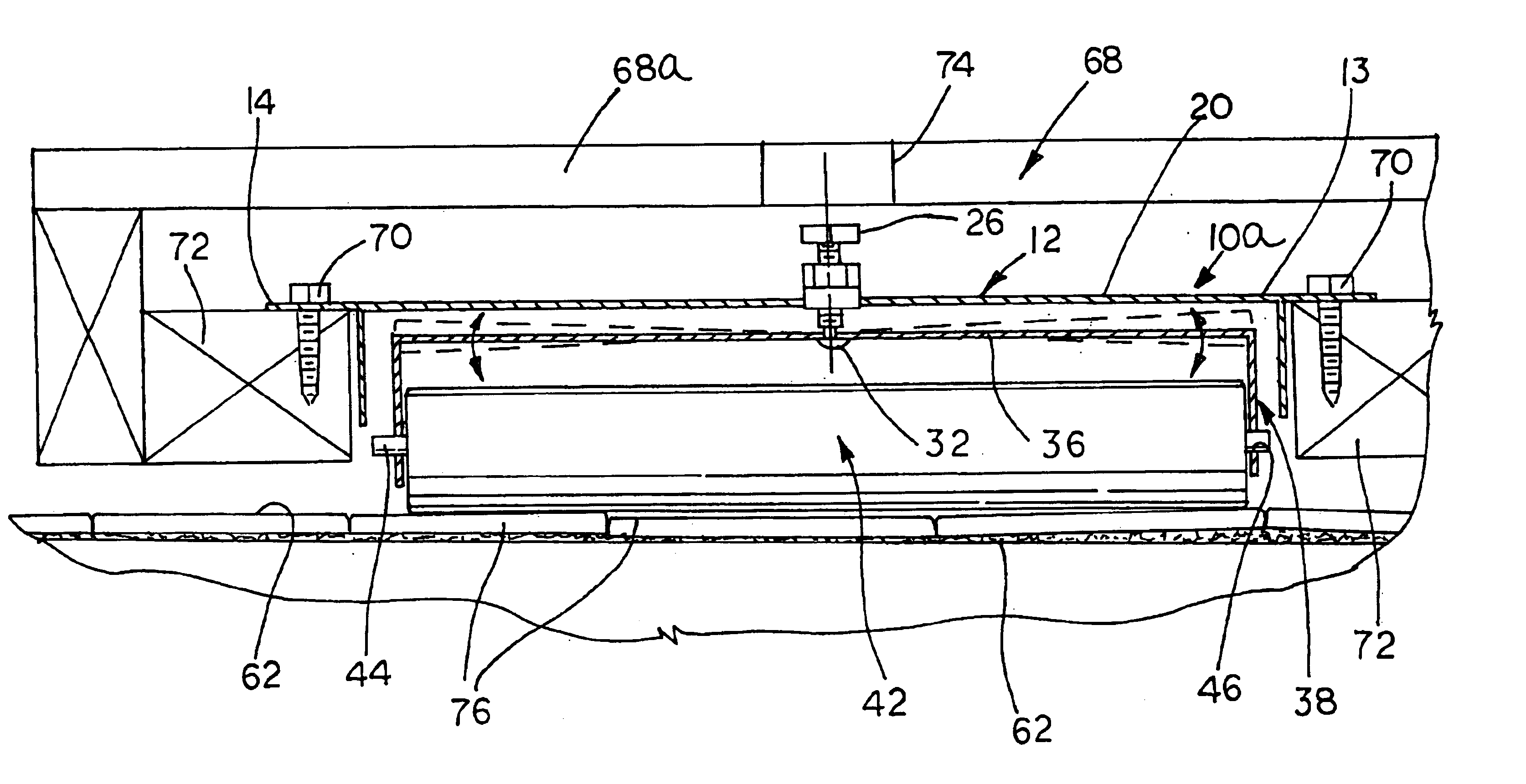
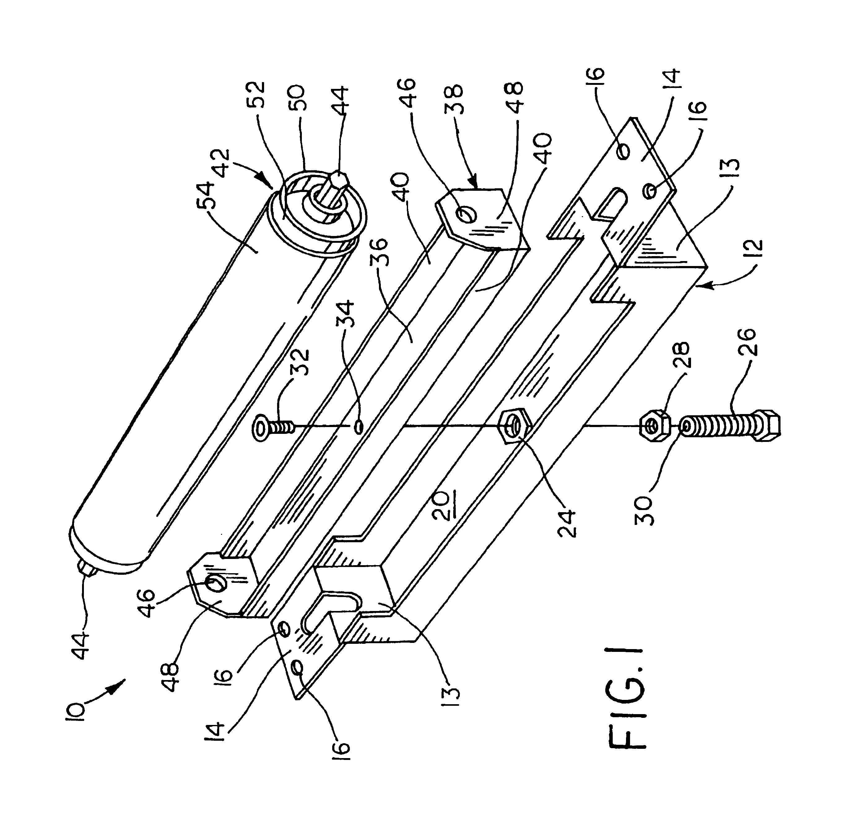
Referring now to the drawings, a roller assembly made pursuant to the teachings of the present invention is generally indicated by the number 10. Roller assembly 10 includes a frame 12 having ends 13 from which project flanges 14 carrying apertures 16 for attaching the frame 12 to the floor of the slide-out room or to the floor of the main living area of the transportable living quarters as will hereinafter be explained. Frame 12 further includes a longitudinal section 20 extending between ends 13. At approximately the center of longitudinal section 20, a nut 24 is secured to the longitudinal section 20 to provide a threaded opening therethrough. Nut 24 receives a threaded bolt 26 upon which a nut 28 is rotatably secured to act as a lock nut to secure the bolt 26 in a preselected position relative to the longitudinal section 20.

The end of the bolt 26 is provided with a threaded aperture 30, which receives screw 32. The length of screw 32 and depth of the bore 30 are such that a rela...


PUM


Abstract

A roller assembly for use with a slide-out room used in mobile homes, manufactured housing and recreational vehicles in which the assembly includes a roller journalled to a carrier. The carrier is mounted to a frame by an adjustable connection which allows a variation position of the carrier relative to the frame. The carrier is connected to the frame for articulated movement so as to allow the carrier and its roller to rock relative to the frame which is adapted for connection to either the slide-out room or the living area which forms a part of the mobile home, manufactured housing or recreational vehicle.

Description

BACKGROUND OF THE INVENTIONMobile living quarters, such as recreational vehicles and manufactured housing, are commonly equipped with a slide-out room which can be retracted into the main living quarters in order to reduce the size of the living unit to that which can be accommodated to travel on public highways, and which may be extended from the main living quarters to provide an auxiliary living area when the unit is parked for use. Increasingly, such mobile living quarters have been provided with luxurious accommodations, such as carpeting, tile floors, and similar floor coverings. Of course, it is necessary that movement of the slide-out room as it is extended or retracted not damage such floor coverings. Furthermore, slide-out rooms must be maintained relatively level both during extension and retraction, and also when parked for use. If the slide-out room becomes out of alignment with the aperture in the main living quarters through which the slide-out room is extended and re...

Claims


Application Information

Patent Timeline
Patent Type & Authority Patents(United States)
IPC IPC(8): B60P3/34B60P3/32E04B1/343
CPCE04B1/34336E04B1/3431B60P3/34
Inventor GARDNER, STEWART
Owner GARDNER STEWART
Why Eureka
Try Eureka