Direct drive for a wheel set

a direct drive and wheel set technology, applied in the direction of locomotive transmission, electric motor propulsion transmission, locomotives, etc., can solve the problems of inconvenient installation of the drive the drive is not suitable for propelling the wheel set with continuous shaft, and the disk-like configuration of the direct drive cannot be used in the available space between the two wheels only with great constructive difficulty, so as to achieve the effect of reducing production costs, less maintenance, and small energy consumption

Inactive Publication Date: 2005-03-22
SIEMENS MOBILITY GMBH
View PDF7 Cites 22 Cited by
  • Summary
  • Abstract
  • Description
  • Claims
  • Application Information

AI Technical Summary

Benefits of technology

The invention is thus based on the object to provide a drive for a wheel set of a chassis, which requires less maintenance works and is more cost-efficient to manufacture compared to conventional drive systems. Moreover, this drive concept should have decreased energy consumption and generate less noise emission. A further object of the invention is the construction of this drive system so as to be useable also in low-platform rail vehicles.
As wheel set and internal rotor motor are internally supported, the chassis can be provided much easier with a sound protection device.

Problems solved by technology

As consequence of its disposition and construction, there is the drawback that this drive is hardly applicable for use in railway vehicles with conventional wheel sets that are supported externally or interiorly.
The drive has to be shifted to the inside between both wheels of the wheel set being driven, whereby the disk-like configuration of this direct drive can be fitted in the available space between both wheel only with great constructive difficulty.
Thus, this drive is not suitable for propelling a wheel set with continuous shaft.

Method used


Image

  • Direct drive for a wheel set
  • Direct drive for a wheel set
  • Direct drive for a wheel set

Examples


Embodiment Construction

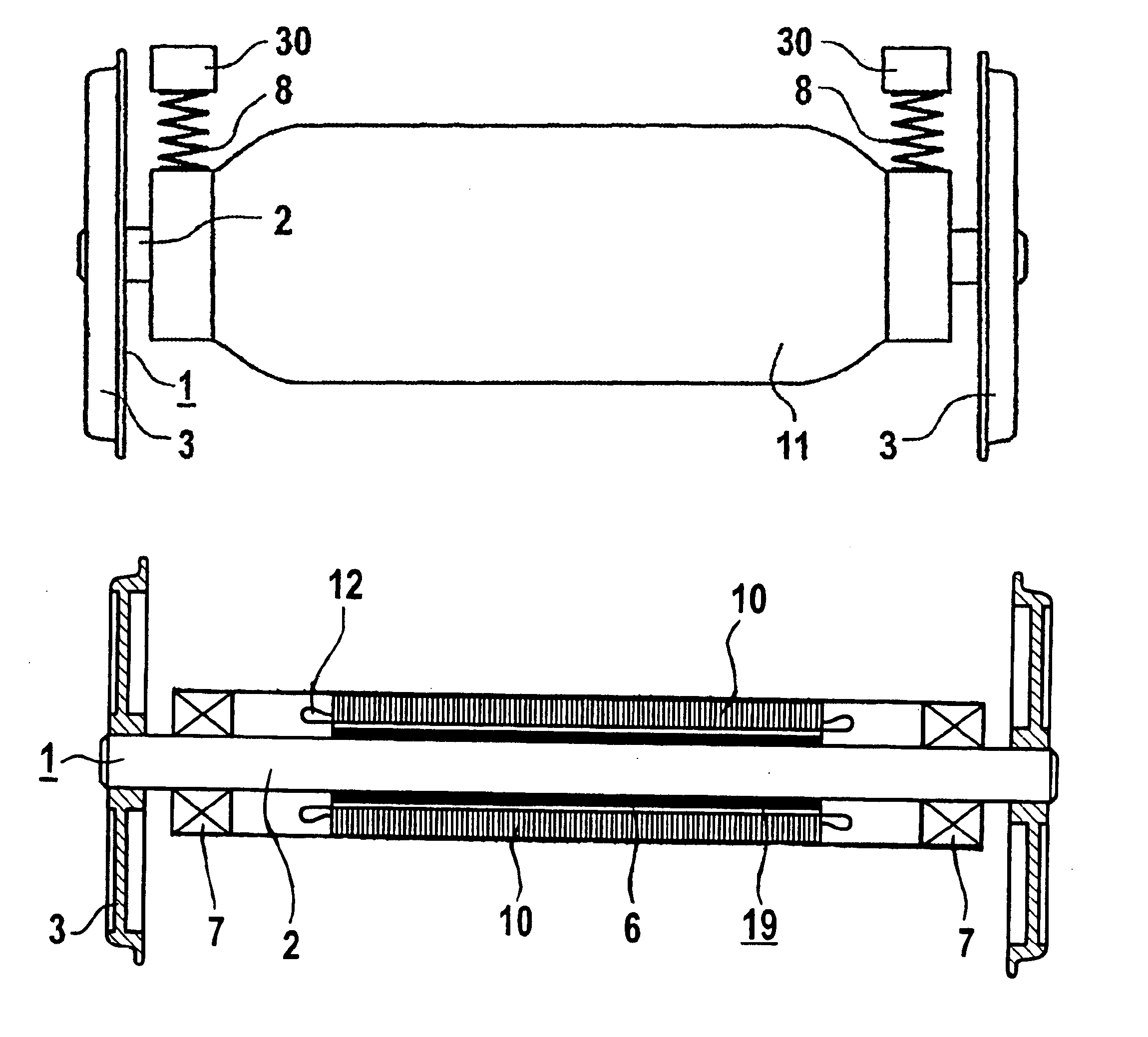
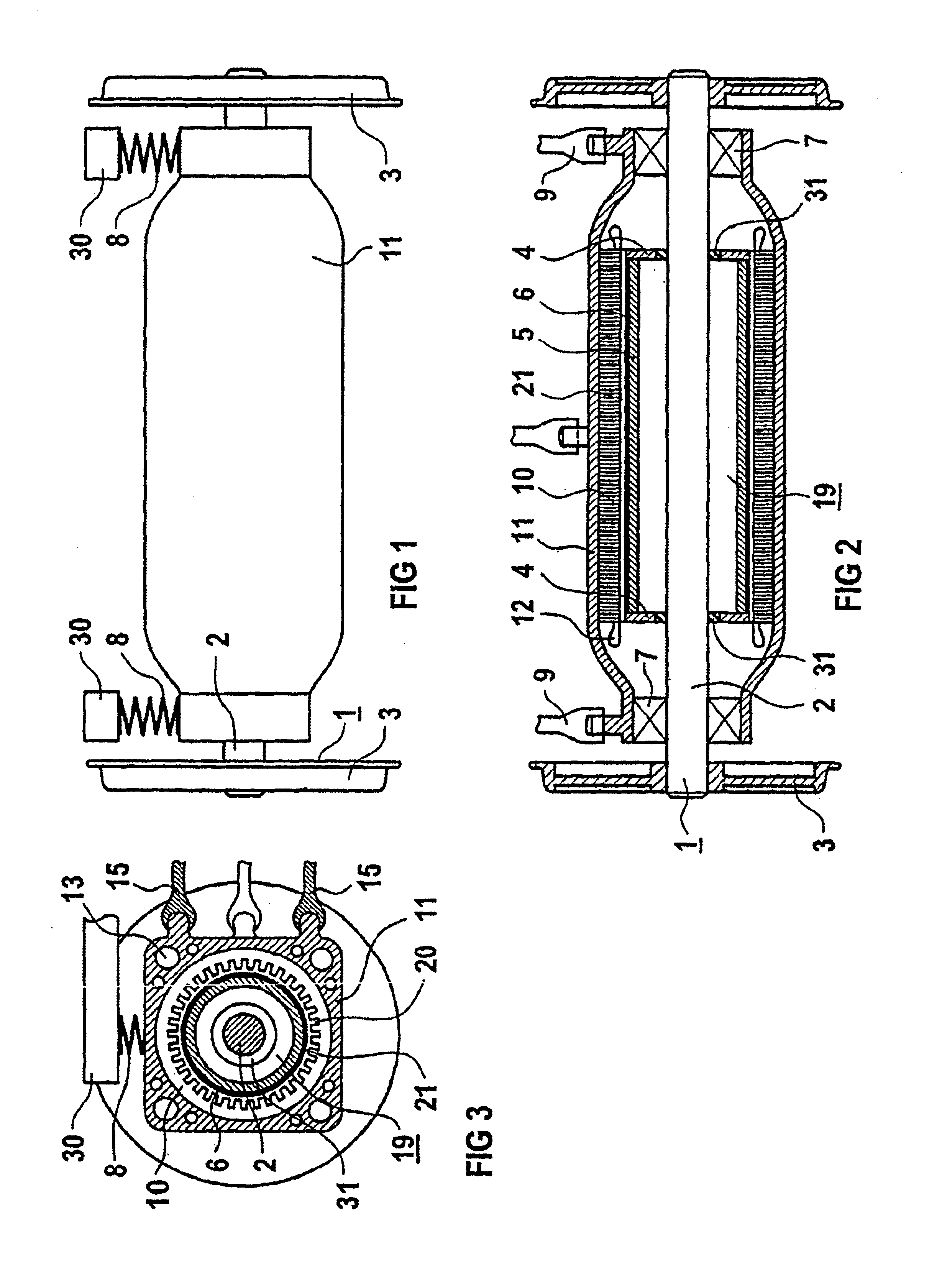
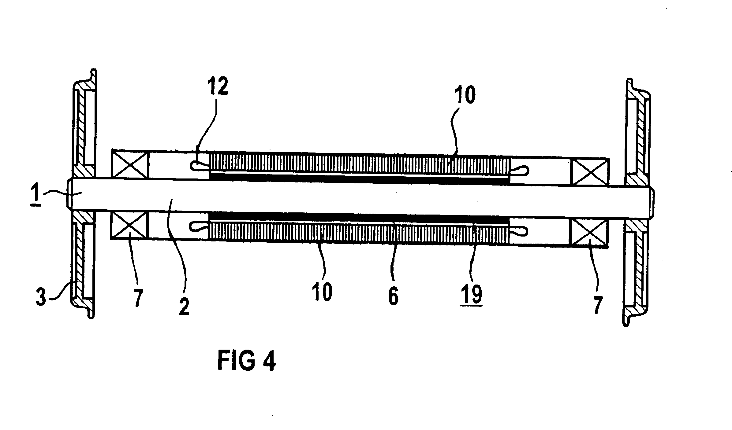
A wheel set 1 of a chassis, not shown in more detail in FIG. 1, includes a wheel set shaft 2 and the wheels 3 mounted to this wheel set shaft 2. The wheels 3 are secured to the wheel set shaft 2, in particular shrunk-on. A rotor 19 of an electric motor configured as internal rotor motor, in particular as synchronous motor, is disposed according to FIG. 2 upon the wheel set shaft 2. The rotor 19 has essentially a tubular configuration and is situated on the wheel set shaft 2 between two steel plates 4. The tubular rotor 19 is hereby made preferably as hollow steel shaft 5 supporting permanent magnets 6 about the surface. Advantageously, the hollow steel shaft 5 is coupled via rubber elements 31 with the wheel set shaft 2. Stator 10 and the rotor 19, which is situated upon the wheel set shaft 2, are mechanically connected via rolling-contact bearings 7. These rolling-contact bearings 7 assume the function wheel set bearing as well as the function driving motor bearing so that only two...


PUM


Abstract

A drive for a wheel set (1) of a chassis includes two wheels (3) positioned on a wheel set shaft (2), which can be driven by at least one internal rotor motor that encompasses the wheel set shaft (2) and has a stator (10) and a rotor (19). This configuration provides a compact direct drive.

Description

BACKGROUND OF THE INVENTIONThe invention relates to a drive for a wheel set of a chassis.EP 0 413 337 A1 discloses an electromotive direct drive for a railway vehicle, having an electronically commutated electric motor placed axially next to the wheel being driven and including a rotor, connected to the wheel being driven, for torque transmission. The rotor and the wheel being driven have rotation axes which are substantially in alignment. Moreover, the rotor is constructed as external rotor of the electric motor in the absence of a housing of the electric motor and is provided with permanent magnets distributed in ring-shaped fashion. Furthermore, the stator of the electric motor is restrained on the vehicle against execution of a rotation on a vehicle side which is distal to the wheel being driven.As consequence of its disposition and construction, there is the drawback that this drive is hardly applicable for use in railway vehicles with conventional wheel sets that are supported...

Claims


Application Information

Patent Timeline
Patent Type & Authority Patents(United States)
IPC IPC(8): B61C9/00B61C9/38B60K7/00B61C9/44B61C9/48H02K9/19H02K21/14
CPCB61C9/38Y02T30/10Y02T30/00
Inventor HOFFMAN, THILOJOCKEL, ANDREASTEICHMANN, MARTIN
Owner SIEMENS MOBILITY GMBH
Why Eureka
Try Eureka