Internal combustion engine with balancer shaft and method of assembling the same

a technology of internal combustion engine and balancer shaft, which is applied in the direction of machines/engines, mechanical equipment, rotary machine parts, etc., can solve the problems of requiring a lot of complicated work, and achieve the effect of reducing or suppressing the secondary vibration of the engin

Active Publication Date: 2005-03-22
NISSAN MOTOR CO LTD +1
View PDF6 Cites 16 Cited by
  • Summary
  • Abstract
  • Description
  • Claims
  • Application Information

AI Technical Summary

Benefits of technology

In installation of the power transmitting mechanism on the crankshaft and the balancer shaft, it is necessitated to make them operate in such a timed relation that can reduce or suppress a secondary vibration of the engine generated by a reciprocating motion of pistons.
It is accordingly an object of the present invention to provide an internal combustion engine with a balancer shaft that enables a power transmitting mechanism to be installed on a crankshaft and a balancer shaft with an easier work.

Problems solved by technology

However, positioning the crankshaft and the balancer shaft in place and installing the power transmitting mechanism so as to attain a desired timed relation between them requires a quite complicated work due to a conventional layout.

Method used


Image

  • Internal combustion engine with balancer shaft and method of assembling the same
  • Internal combustion engine with balancer shaft and method of assembling the same
  • Internal combustion engine with balancer shaft and method of assembling the same

Examples


Embodiment Construction

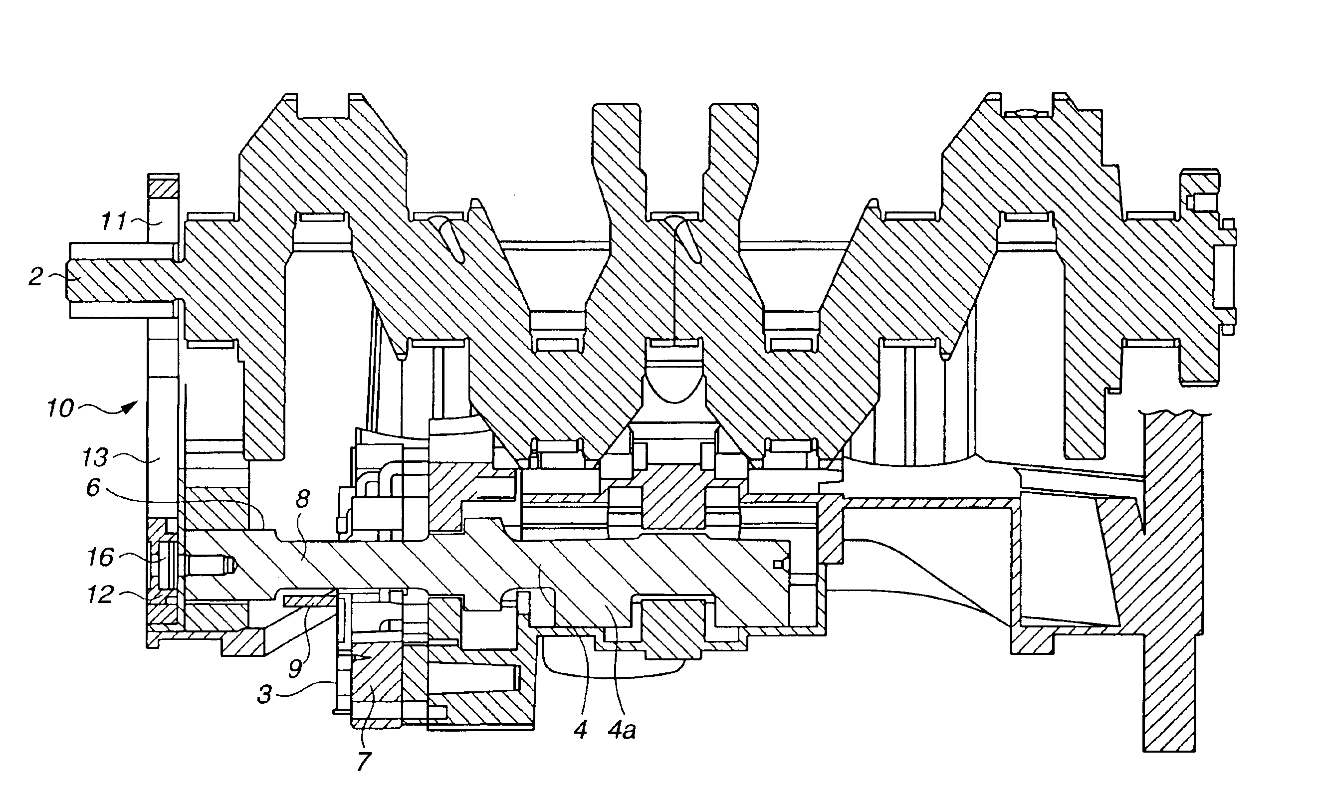
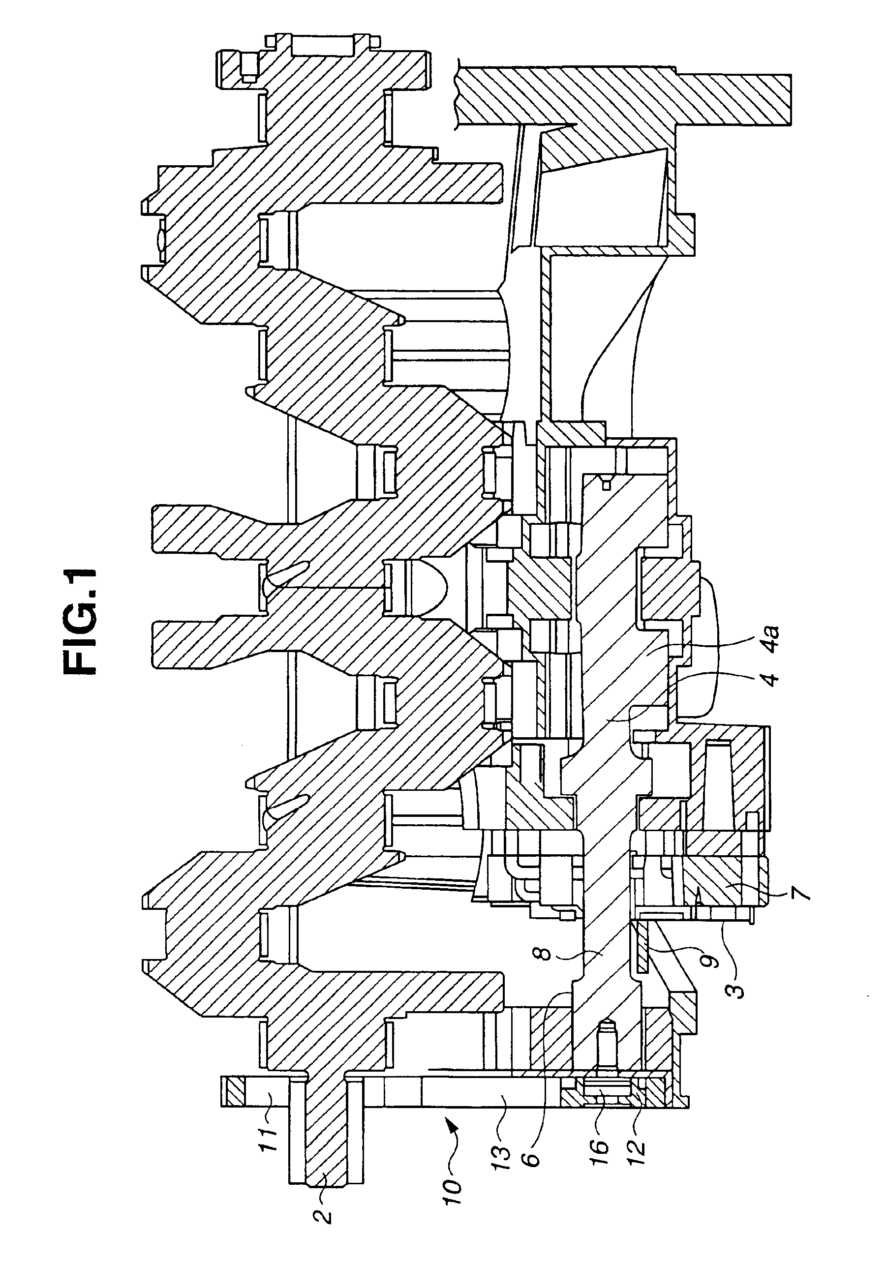
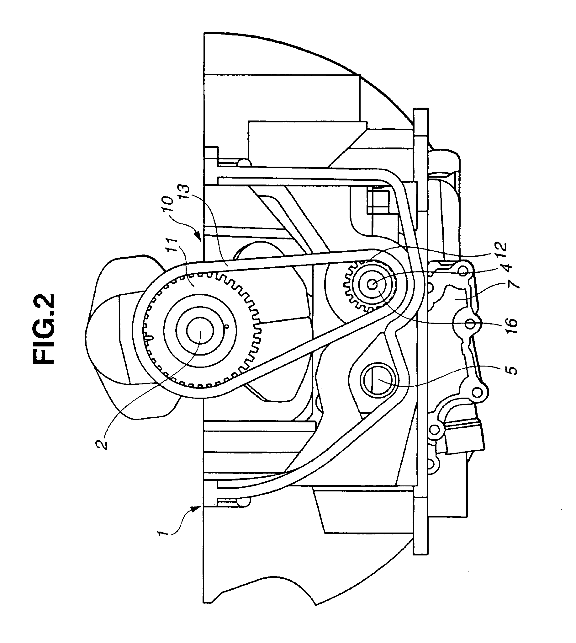
Referring to FIGS. 1 to 6, inclusive, an in-line four-cylinder internal combustion engine includes engine block 1, crankshaft 2 rotatably installed on a lower portion of engine block 1 and balancer housing 3 disposed under crankshaft 2. Disposed within balancer housing 3 in parallel with crankshaft 2 are drive side and driven (follower) side balancer shafts 4, 5 having eccentric balancer weight portions 4a.

Balancer shafts 4, 5 have reverse gears (not shown) that are meshed with each other so as to rotate in opposite directions. By this, rotation of drive side balancer shaft 4 causes driven side balancer shaft 5 to rotate in timed relation thereto.

Drive side balancer shaft 4 has an end portion (i.e. a left-hand end side end portion in FIG. 1) 6 that protrudes outward of balancer housing 3. End portion 6 is partly cut so as to form flattened section 8 used for positioning of balancer shaft 4. More specifically, end portion 6 is cut at diametrically opposite sections so that flattened...


PUM

PropertyMeasurementUnit
lengthaaaaaaaaaa
weightaaaaaaaaaa
rotationaaaaaaaaaa

Abstract

An internal combustion engine includes a balancer housing, a balancer shaft having an eccentric weight portion and disposed within the balancer housing so as to be parallel with and rotatable in timed relation with a crankshaft, and a power transmitting mechanism that transmits rotation of the crankshaft to the balancer shaft, wherein the balancer shaft has an end portion protruding outward of the balancer housing, and wherein the end portion of the one balancer shaft is partially cut to have a flattened section that constitutes a device for positioning the balancer shaft in a predetermined rotational position. A method of assembling an internal combustion engine with a balancer shaft is also provided.

Description

BACKGROUND OF THE INVENTIONThe present invention relates to an internal combustion engine with a balancer shaft and a method of assembling the same.An internal combustion engine with a pair of balancer shafts is disclosed in Japanese Patent Provisional Publication No. 6-33989. In the engine, a balancer housing is disposed under an engine block. A drive side balancer shaft and driven side drive balancer shaft having respective eccentric weight portions are disposed within the balancer housing so as to be parallel with a crankshaft and rotatable in timed relation with each other. Between the crankshaft and the drive side balancer shaft is disposed a power transmitting mechanism including a pair of sprockets and a chain for transmitting rotation of the crankshaft to the drive side balancer shaft.Namely, one of the sprockets is installed on the end portion of the crankshaft and the other is installed on the end portion of the drive side balancer shaft. Then, the chain is wound around th...

Claims


Application Information

Patent Timeline
Patent Type & Authority Patents(United States)
IPC IPC(8): F16F15/22F16F15/26F16C3/02F01M1/02
CPCF16F15/264Y10T29/49231Y10T464/50F16C3/02
Inventor HIRAKI, NOBUYUKITANIAI, HIROYUKI
Owner NISSAN MOTOR CO LTD
Why Eureka
Try Eureka