Supercharge Your Innovation With Domain-Expert AI Agents!

Engine blowby gas processing system

Active Publication Date: 2005-03-22
HONDA MOTOR CO LTD
View PDF5 Cites 11 Cited by
  • Summary
  • Abstract
  • Description
  • Claims
  • Application Information

AI Technical Summary

Benefits of technology

An object of the present invention is to provide an engine blowby gas processing system having a simplified structure.
An object of the present invention is to provide a low cost, engine blowby gas processing system enabling oil to be separated from the blowby gas without inserting a special oil separator tank on the way to a breather tube.

Problems solved by technology

In addition, the engine in some way must support the tank, additional structure is required to be provided, e.g., the number of parts is increased, and the cost is increased.

Method used


Image

  • Engine blowby gas processing system
  • Engine blowby gas processing system
  • Engine blowby gas processing system

Examples


Embodiment Construction

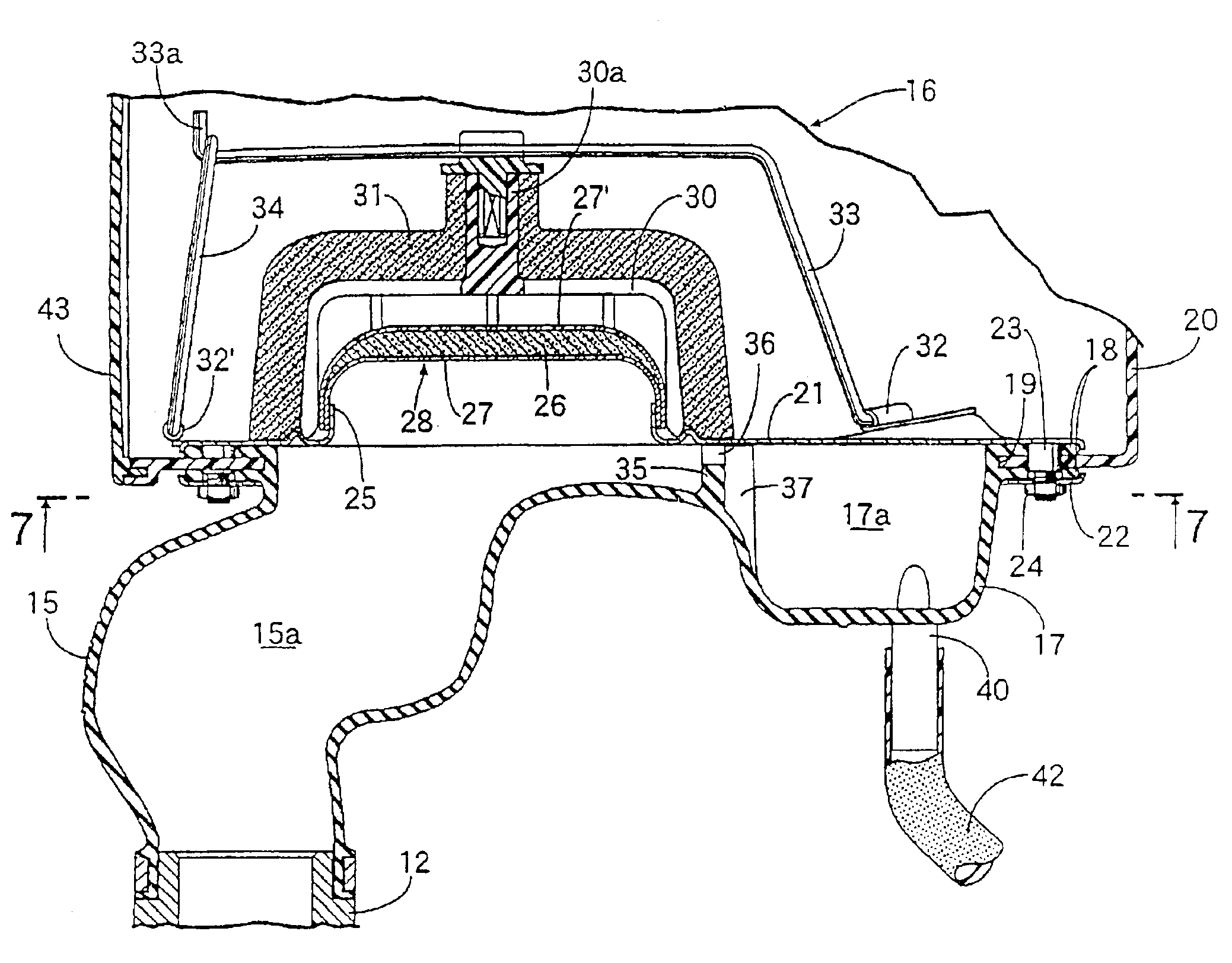
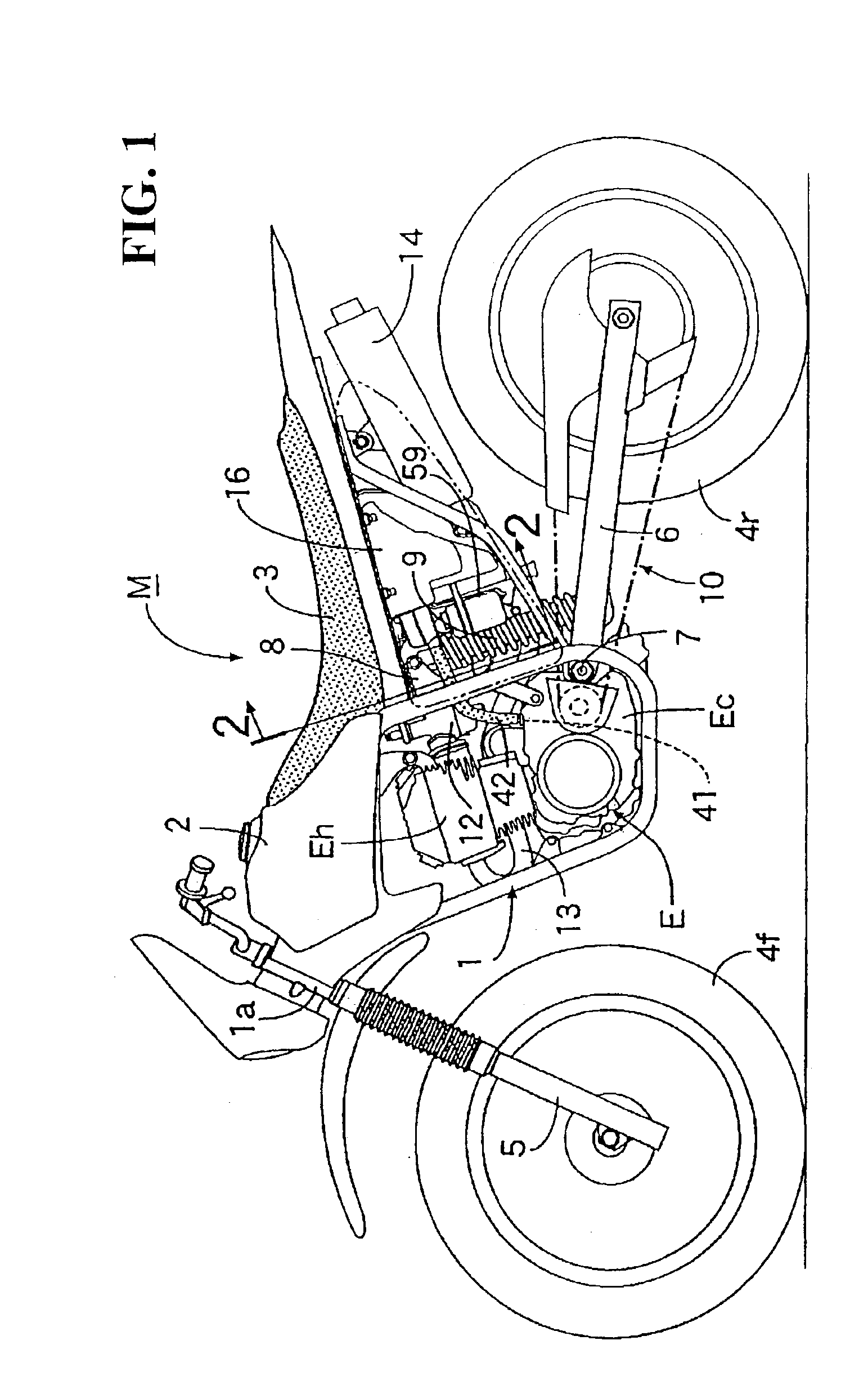
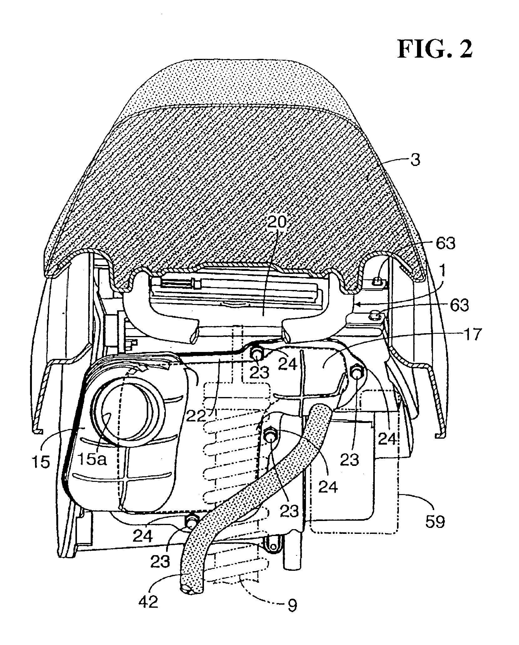
The present invention will hereinafter be described with reference to the accompanying drawings. FIG. 1 is a left side view showing a motorcycle provided with a blowby gas processing system according to an embodiment of the present invention. FIG. 2 is an enlarged sectional view viewed along a line 2—2 in FIG. 1. FIG. 3 is an enlarged view showing a main part of a portion shown in FIG. 2. FIG. 4 is a view taken along a direction shown by an arrow 4 in FIG. 3. FIG. 5 is a side view showing a periphery of an air cleaner viewed from the side opposite to the side shown in FIG. 1. FIG. 6 is a sectional view taken along a line 6—6 in FIG. 3. FIG. 7 is a sectional view taken along a line 7—7 in FIG. 6. FIG. 8 is an end view with respect to the upstream side of a connecting tube. FIG. 9 is an enlarged view taken along a direction shown by an arrow 9 in FIG. 3. FIG. 10 is an enlarged view showing a main part of a portion shown in FIG. 4. FIG. 11 is a sectional view viewed along a line II—II ...


PUM


Abstract

A blowby gas processing system includes a breather tube extended from a breather port of an engine and connected to a connecting tube. A breather tube inside which an intake passage connecting a carburetor and an air cleaner is formed and an expanded part provided with a gas-liquid separating chamber adjacent to the intake passage are provided. An entrance joint connecting a lower part of the gas-liquid separating chamber to the breather tube is integrated on one side of the connecting tube and a blowby gas exit communicating the upside of the gas-liquid separating chamber with the intake passage is provided in a partition between the gas-liquid separating chamber and the intake passage. The system is a low cost system having a simplified design enabling oil to be separated from blowby gas without having to include a special oil separator tank before the breather tube.

Description

BACKGROUND OF THE INVENTIONCROSS-REFERENCES TO RELATED APPLICATIONSThis nonprovisional application claims priority under 35 U.S.C. § 119(a) on patent application Ser. No. 2002-167621 filed in Japan on Jun. 7, 2002, the entirety of which is herein incorporated by reference.1. Field of the InventionThe present invention relates to a system for processing blowby gas of an engine, and more particularly to the improvement of a system in which a breather tube extending from a breather port for exhausting blowby gas of an engine is connected to a connecting tube. An intake passage connecting a carburetor and an air cleaner is formed inside the connecting tube, and blowby gas in a crankcase of the engine is circulated in the engine through the breather tube and the intake passage during a combustion cycle of the engine.2. Description of the Background ArtJapanese published examined patent application No. 2639604 describes an engine blowby gas processing system of the background art in which...

Claims


Application Information

Patent Timeline
IPC IPC(8): F02M25/06F02B61/02F02B61/00F02M35/10F01M13/00F02M35/024
CPCF02B61/02F02M25/06F02M35/10013F02M35/10222F02M35/161F02M35/10196Y02T10/121Y02T10/12
Inventor YASUI, HISAKAZU
Owner HONDA MOTOR CO LTD
Features
  • R&D
  • Intellectual Property
  • Life Sciences
  • Materials
  • Tech Scout
  • Unparalleled Data Quality
  • Higher Quality Content
  • 60% Fewer Hallucinations
Learn More