Rotary sprinkler with arc adjustment guide and flow-through shaft

a technology of arc adjustment guide and flow-through shaft, which is applied in the direction of spraying apparatus, liquid transfer device, moving device, etc., can solve the problems of difficult or unnatural adjustment, difficult or difficult to read, and difficult to manufacture leaf springs, etc., and achieve the effect of easy attachment of the sprayer

Inactive Publication Date: 2005-03-22
TORO CO THE
View PDF6 Cites 61 Cited by
  • Summary
  • Abstract
  • Description
  • Claims
  • Application Information

AI Technical Summary

Benefits of technology

Yet another aspect of this invention is to provide a rotary drive for a sprinkler that can be easily built in intermittent or continuous drive versions. A continuous drive version is built in which all the gears are normal rotary gears with regularly shaped teeth. To build the intermittent version of the drive, a few of the normal rotary gears in the continuous drive version of the drive are replaced with multilated gears.
Another aspect of this invention relates to a friction clutch for preventing damage to a rotary sprinkler drive during periods of forced nozzle rotation. Such a friction clutch includes opposed sets of teeth on the clutch members with the teeth being asymmetrically arranged relative to one another. An O-ring is placed between the teeth of the clutch members. In yet another aspect of this invention, the O-ring is pre-lubricated in an oil to compensate for the effects of the contaminants typically found in the water flowing through the sprinkler.
Another aspect of this invention relates to a rotary sprinkler having a rotary nozzle assembly in which the nozzle is pivotal to have its trajectory adjusted. In this aspect of the invention, the pivotal nozzle is carried in a cradle that also carries a radius adjustment screw so that the radius adjustment screw pivots with the nozzle to maintain a fixed relationship to the nozzle once the screw has been adjusted. In yet another aspect of this invention, the radius adjustment screw has an enlarged head carried on top of a flexible portion of the cover which flexible cover portion can tilt or flex relative to the rest of the cover as the nozzle trajectory changes. This permits the radius adjustment screw to be operated from above the sprinkler despite any changes in the nozzle trajectory.
Another aspect of this invention relates to a stream straightener having flow straightening vanes to lessen any disturbance which the stream straightener might otherwise impose on the water flowing through the sprinkler.
Yet another aspect of this invention relates to a removable member that can be attached to a sprinkler to more easily attach the sprinkler to an upstanding stake for above ground installation of the sprinkler.

Problems solved by technology

This can make them somewhat difficult to read.
In adjusting one stop relative to another, the adjustable stop(s) are often necessarily ratcheted over serrations or detents, thus making adjustment somewhat difficult or unnatural.
Such leaf springs are somewhat difficult to manufacture and are somewhat less durable than would otherwise be desirable.
However, such nozzle assemblies have not included those which use radius adjustment screws to selectively break up the stream from the nozzle to shorten the radius.
Such nozzle assemblies equipped with radius adjustment screws have not been adjustable in trajectory.
Such an elongated member disturbs the water stream flowing through the nozzle, which is obviously undesirable.
Such indicia have in the past been difficult to read.

Method used


Image

  • Rotary sprinkler with arc adjustment guide and flow-through shaft
  • Rotary sprinkler with arc adjustment guide and flow-through shaft
  • Rotary sprinkler with arc adjustment guide and flow-through shaft

Examples


Embodiment Construction

Introduction

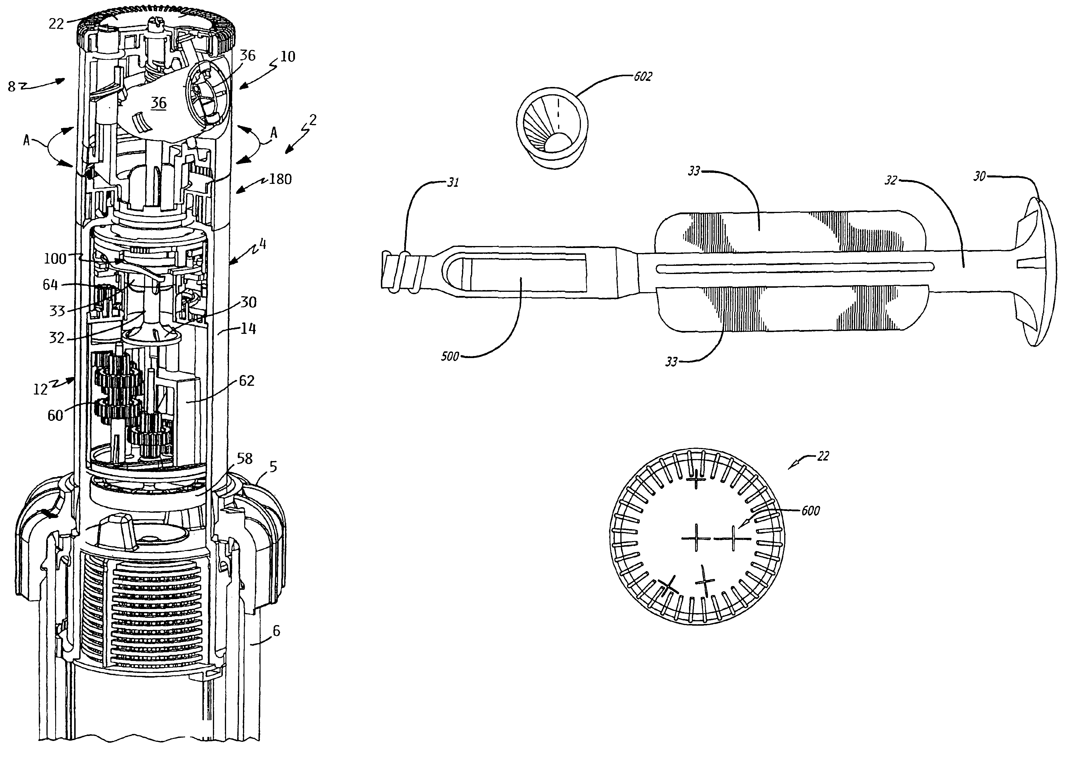
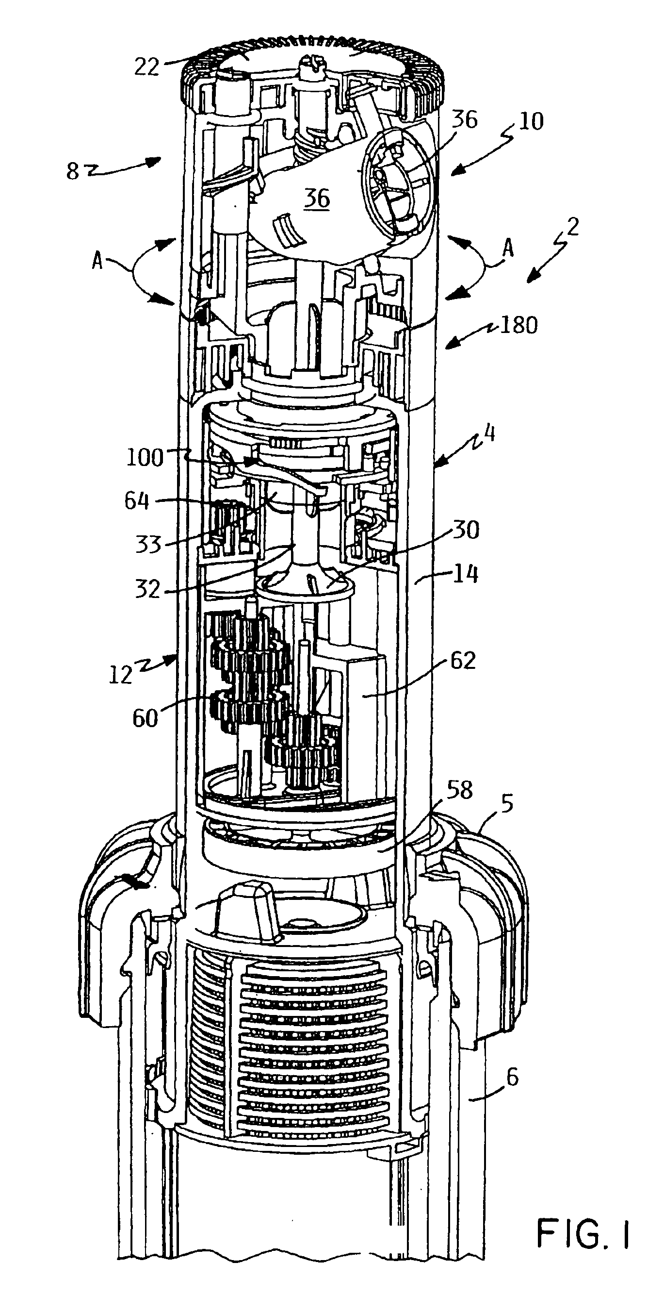
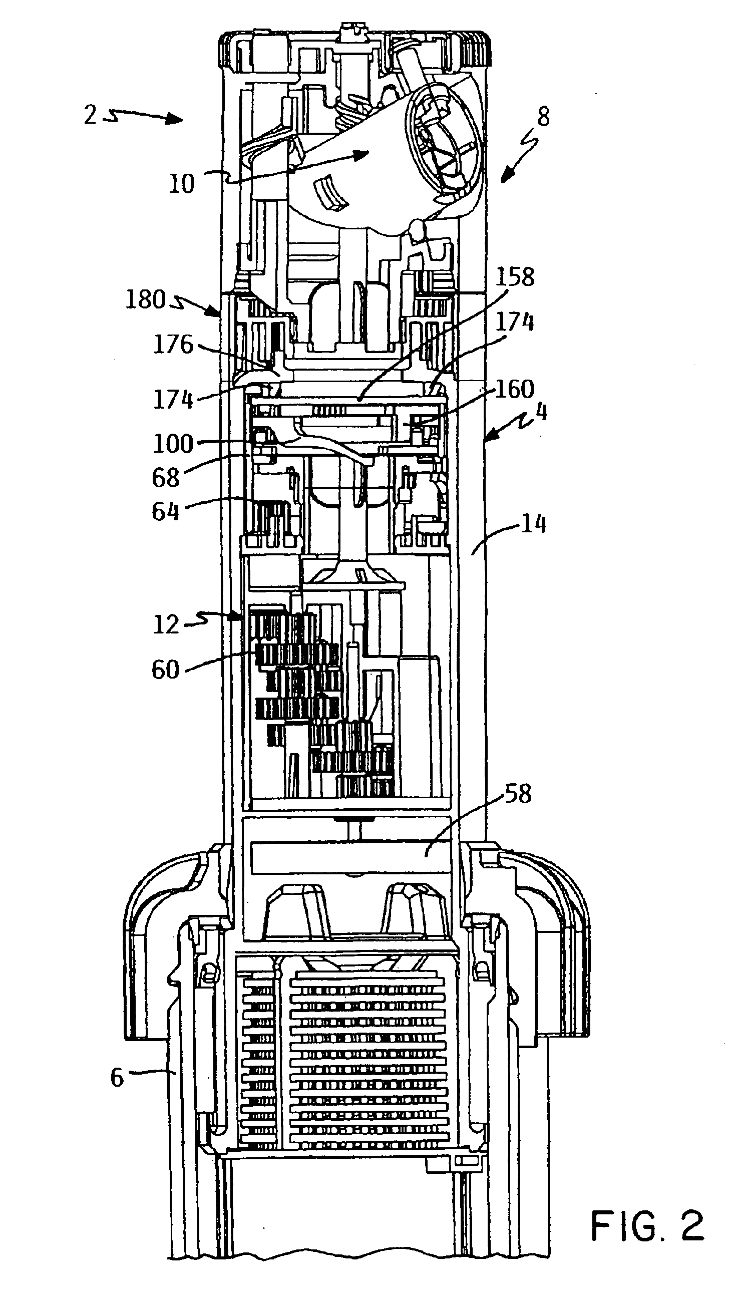
Referring first to FIGS. 1 and 2, this invention relates to a water sprinkler, generally identified as 2 in the drawings, for irrigating an area of ground or turf. Sprinkler 2 preferably comprises a pop-up sprinkler in which a pop-up riser 4 is reciprocally carried within an outer sprinkler body 6. When water pressure is not present within the interior of sprinkler body 6, riser 4 is retracted by a retraction spring (not shown) within sprinkler body 6 so that the top of riser 4 is generally flush with a cap 5 on the top of sprinkler body 6. However, when water pressure is present within sprinkler body 6, as when a valve upstream of sprinkler body 6 or within the water inlet of sprinkler body 6 in the case of a valve-in-head sprinkler is opened, such water pressure acts against riser 4 to pop riser 4 up out of sprinkler body 6. FIGS. 1 and 2 illustrate riser 4 in its popped up orientation. When riser 4 pops up, a nozzle assembly 8 at the top of riser 4 is exposed to allow...


PUM


Abstract

A rotary sprinkler having an adjustable arc segment whose angular extent and absolute direction relative to the ground are represented by an arc indicator, which arc indicator may comprise a band whose visible length represents the angular extent and whose position on the sprinkler points to the direction. The sprinkler may have the arc segment adjusted by a movable arc limit stop that is coupled to a toggle member only at drive reversal, and the sprinkler may be converted to full circle operation by raising the arc limit stop relative to a cooperating trip tab. A buckling spring assembly used to shift the drive comprises a compression spring held between two spaced pivot members, and the drive can be built in continuous and intermittent drive versions by replacing a few normal rotary gears with multilated gears. A friction clutch having asymmetric teeth for smooth operation prevents damage to the drive during forced nozzle rotation. A nozzle assembly includes a pivotal nozzle that carries a radius adjustment screw with the head of the screw received on top a flexible portion of a top cover, which top cover has laser etched indicia relating to various adjustments of the sprinkler. A flow shut off valve includes stream straightening vanes and a collar may be used to support the sprinkler on a stake or post for above ground installation.

Description

TECHNICAL FIELDThis invention relates to a rotary sprinkler having a rotatable nozzle assembly for watering an arc of ground traversed or swept by the nozzle assembly as the nozzle assembly rotates. More particularly, this invention relates to a sprinkler of this type in which the trajectory of the water being thrown by the nozzle assembly can be easily adjusted, in which the arc of ground being watered by the nozzle assembly can be easily adjusted, and which includes an indicator for indicating both the angular extent and the direction of the arc of ground being watered by the nozzle assembly, among other things.BACKGROUND OF THE INVENTIONRotary sprinklers are known which have rotary nozzle assemblies that oscillate back and forth through an adjustable arc of rotation to water an adjustable arc segment on the ground. Some such sprinklers have indicators for indicating to the user the angular extent of the arc segment that has been set by the user. These indicators are typically car...

Claims


Application Information

Patent Timeline
Patent Type & Authority Patents(United States)
IPC IPC(8): B05B3/04B05B3/02B05B1/30B05B1/26B05B1/32
CPCB05B1/304B05B3/0431B05B1/265B05B15/10B05B1/32B05B15/74
Inventor MCKENZIE, JEFFMCCORMICK, CHAD PHILIPJANKU, PETER
Owner TORO CO THE
Why Eureka
Try Eureka