
Eccentric work piece holder and method of making same

a work piece and holder technology, applied in the direction of chucks, mechanical equipment, manufacturing tools, etc., can solve the problems of compromising the precision and accuracy of finished pieces, adding more wear to cutting tools, machining errors on work pieces, etc., and achieve the effect of quick and precise removal of radial runou

Inactive Publication Date: 2005-03-22
EASTMAN KODAK CO
View PDF16 Cites 3 Cited by
  • Summary
  • Abstract
  • Description
  • Claims
  • Application Information

AI Technical Summary

Benefits of technology

Another object of the invention is to provide a work piece holder that compensates for work piece run-out during operation.
The present invention has the following advantages: In applications where concentric alignment is needed between a rotary axis and a cylindrical part, the disclosed device provides a means for quick and precise removal of radial runout by allowing eccentric adjustment along two perpendicular axes. The device is compact and lightweight consisting of only three small disks or plates, thus providing advantage for applications that have weight limitations and / or space constraints.

Problems solved by technology

If the work piece is not aligned correctly at the beginning of the operation, precision and accuracy of the finished piece is compromised.
This results in machining errors on the work piece, and also adds more wear to the cutting tool.
Since the motion is uneven, the edge of the tool is not worn evenly.
Relocation of the work piece by tapping it back and forth may result in adjustment overshoot and further misalignment in other directions, thus requiring additional alignment.
These steps cost time and energy and often results in frustration
Different types of work pieces with different tool ends would not be acceptable.
The size of most of the devices cited in the aforementioned patents cannot be adjusted significantly.
Because of the mechanisms built into the toolholder or the tool end, reducing the size of the device would be difficult if not impossible.
These devices cannot be made significantly smaller.
Skilled artisans will appreciate that there are other devices made for specialized purposes and, although effective for their specialties, offer no versatility.
Such process steps add complexity and time consuming adjustment to such an alignment operation.

Method used


Image

  • Eccentric work piece holder and method of making same
  • Eccentric work piece holder and method of making same
  • Eccentric work piece holder and method of making same

Examples


Embodiment Construction

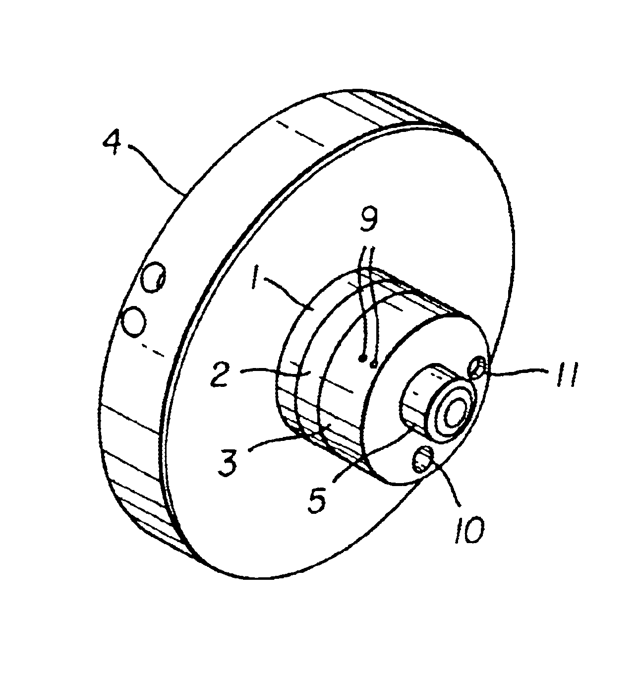
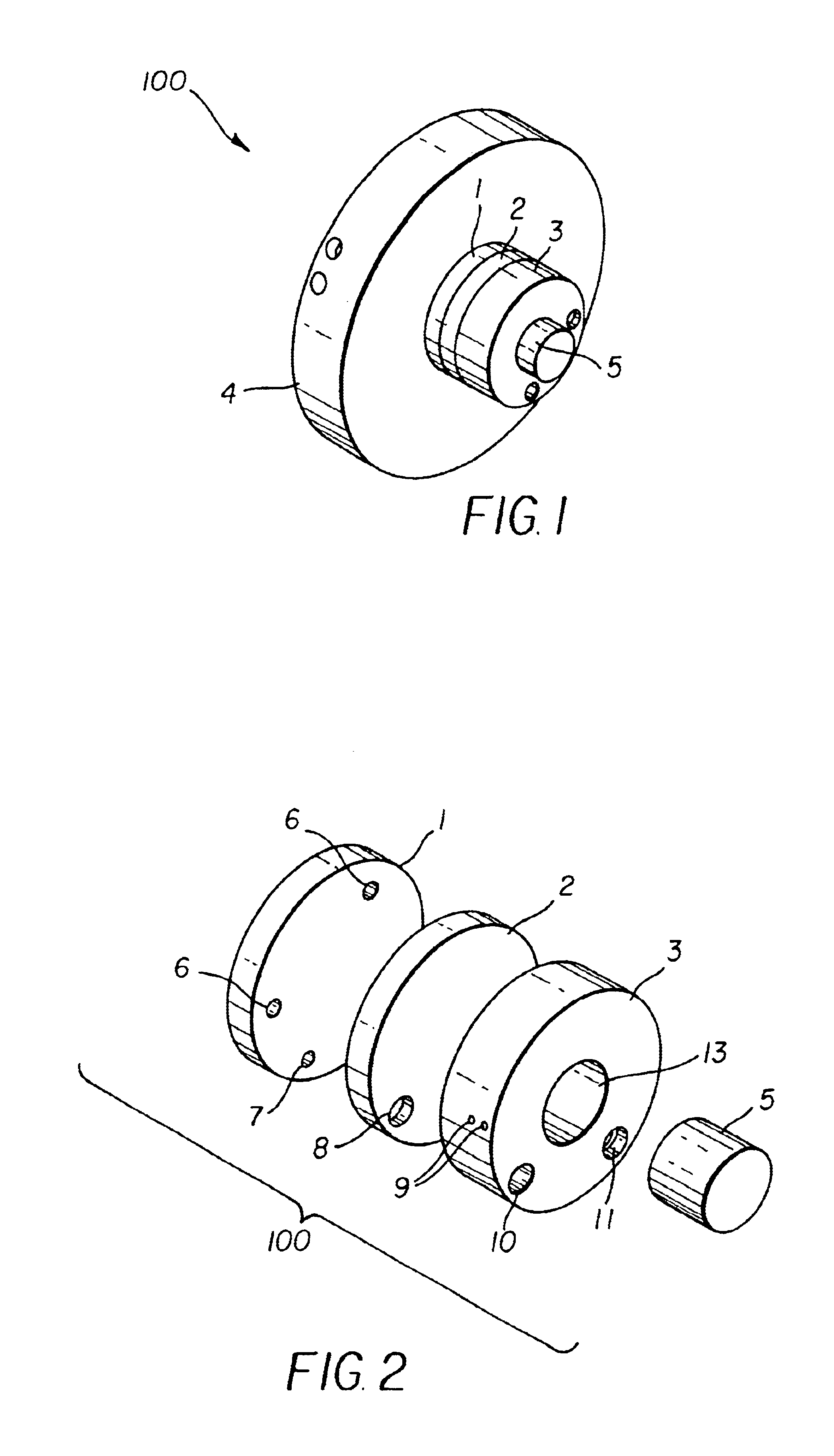
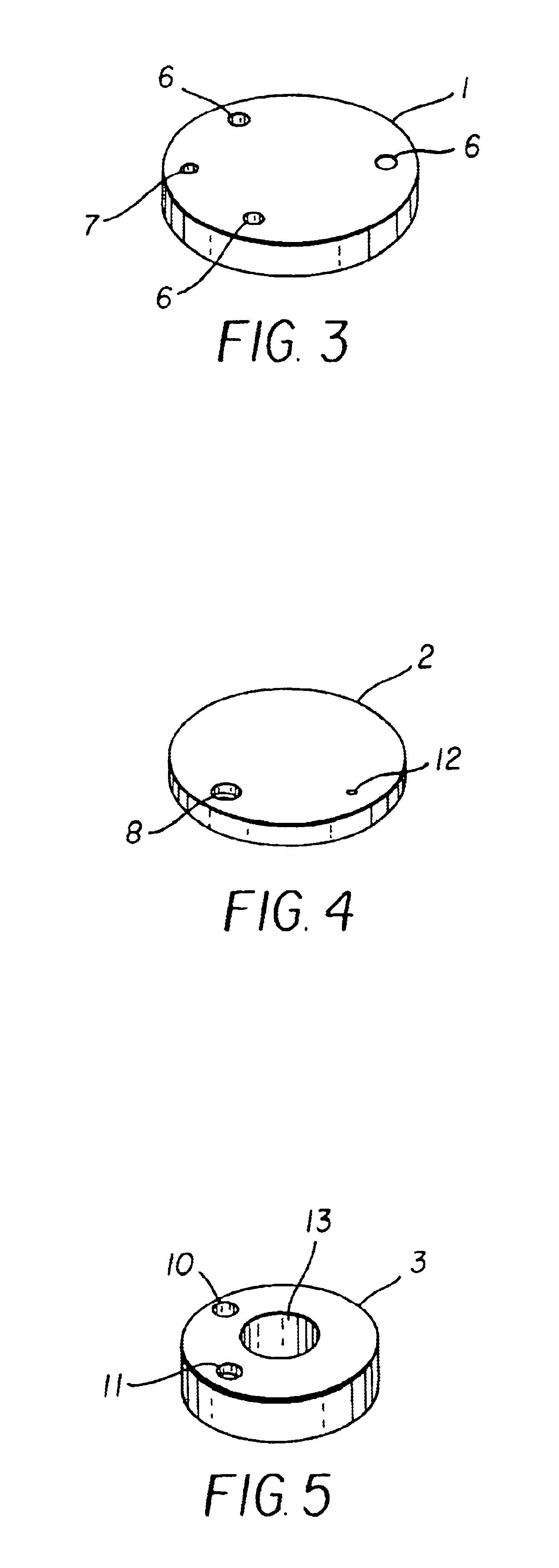
Turning now to the drawings, and in particular to FIGS. 1 and 2, the eccentric work piece holder 100 of the invention is illustrated. Broadly defined, eccentric work piece holder 100 is adaptable to a rotary unit (not shown). Rotary unit has a rotary axis 4 for rotating the work piece 5 during operation. A first aligning member 1 is fixedly mounted on the rotary axis 4 of the rotary unit. A second aligning member 2 is mounted for substantially X-directional pivotal movements along the rotary axis 4. The second aligning member 2 is arranged adjacent to the first aligning member 1. A third aligning member 3, being arranged nearest adjacent to the second aligning member 2, has a bore opening 13 for holding the work piece 5. Further, a third aligning member 3 is mounted for substantially Y-directional pivotal movement along the rotary axis 4. Rotary movement of the first-, second- and third aligning members 1, 2, 3, respectively, along the rotary axis 4 causes the work piece 5, secured ...


PUM

PropertyMeasurementUnit
timeaaaaaaaaaa
energyaaaaaaaaaa
sizeaaaaaaaaaa

Abstract

An eccentric work piece holder supports a work piece in alignment during rotary operations. First-, second- and third aligning members, associated with the rotary axis of a rotary unit, provides pivoting movements relative to the rotary axis while bearing the work piece. These pivoting movements of the aligning members enable the work piece to be aligned during rotary operations.

Description

FIELD OF THE INVENTIONThe invention relates generally to the field of work piece alignment, and in particular to work piece alignment on turning machines. More specifically, the invention relates to work piece alignment on turning machines to remove radial misalignment (runout) between the work piece and the rotary axis.BACKGROUND OF THE INVENTIONIn turning machines, such as lathes, ultra-precision grinders, and single point diamond turning machines, the work piece must be lined up exactly with the rotary axis to which it is attached. If the work piece is not aligned correctly at the beginning of the operation, precision and accuracy of the finished piece is compromised. The movements of the cutting tool are set precisely to coincide with the alignment of the rotary axis of the toolholder, and therefore, the work piece must be lined up exactly with the rotary axis of the toolholder for the machining operation to be successful.Runout, characterized by uneven off-center motion, occurs...

Claims


Application Information

Patent Timeline
Patent Type & Authority Patents(United States)
IPC IPC(8): B23Q1/25B23Q1/54B23Q3/18B23B31/34B23B31/02B23B31/36
CPCB23B31/36B23Q1/5468B23Q3/183B23B2265/12Y10T82/10Y10T279/26Y10T279/25
Inventor MEISSNER, STEPHEN C.BROST, RANDOLPH C.
Owner EASTMAN KODAK CO
Learn More