Method and apparatus to facilitate auto-alignment of images for defect inspection and defect analysis

a technology of image alignment and defect detection, applied in the field of integrated circuit image inspection, can solve the problems of limiting the quality of the found position, slow auto-correlation process, and low success rate of auto-correlation, and achieve the effect of facilitating image auto-alignmen

Inactive Publication Date: 2005-03-22
SYNOPSYS INC
View PDF9 Cites 16 Cited by
  • Summary
  • Abstract
  • Description
  • Claims
  • Application Information

AI Technical Summary

Benefits of technology

One embodiment of the invention provides a system that facilitates auto-alignment of images for defect inspection and defect analysis. The system operates by first receiving a reference image and a test image. Next, the system creates a horizontal cut line across the reference image. The system then chooses a vertical feature on the reference image with a specified width along the horizontal cut line. Next, the system determines that the vertical feature substantially maintains the specified width over a specified range above and below the horizontal cut line. The system also creates a vertical cut line across the reference image. The system then chooses a horizontal feature on the reference image with the specified width along the vertical cut line. Next, the system determines that the horizontal feature substantially maintains the specified width over a specified range left and right of the vertical cut line. Finally, the system locates the vertical feature and the horizontal feature on the test image so that the reference image and the test image can be aligned to perform defect inspection and defect analysis.

Problems solved by technology

Auto-correlation is a very slow process because it requires a computationally intensive mathematical process to be performed pixel-by-pixel on the images.
Also, the success rate of auto-correlation is not very high.
This is an intensive calculation and the range of the shifted positions that are tried will limit the quality of the found position.

Method used


Image

  • Method and apparatus to facilitate auto-alignment of images for defect inspection and defect analysis
  • Method and apparatus to facilitate auto-alignment of images for defect inspection and defect analysis
  • Method and apparatus to facilitate auto-alignment of images for defect inspection and defect analysis

Examples


Embodiment Construction

Integrated Circuit Images

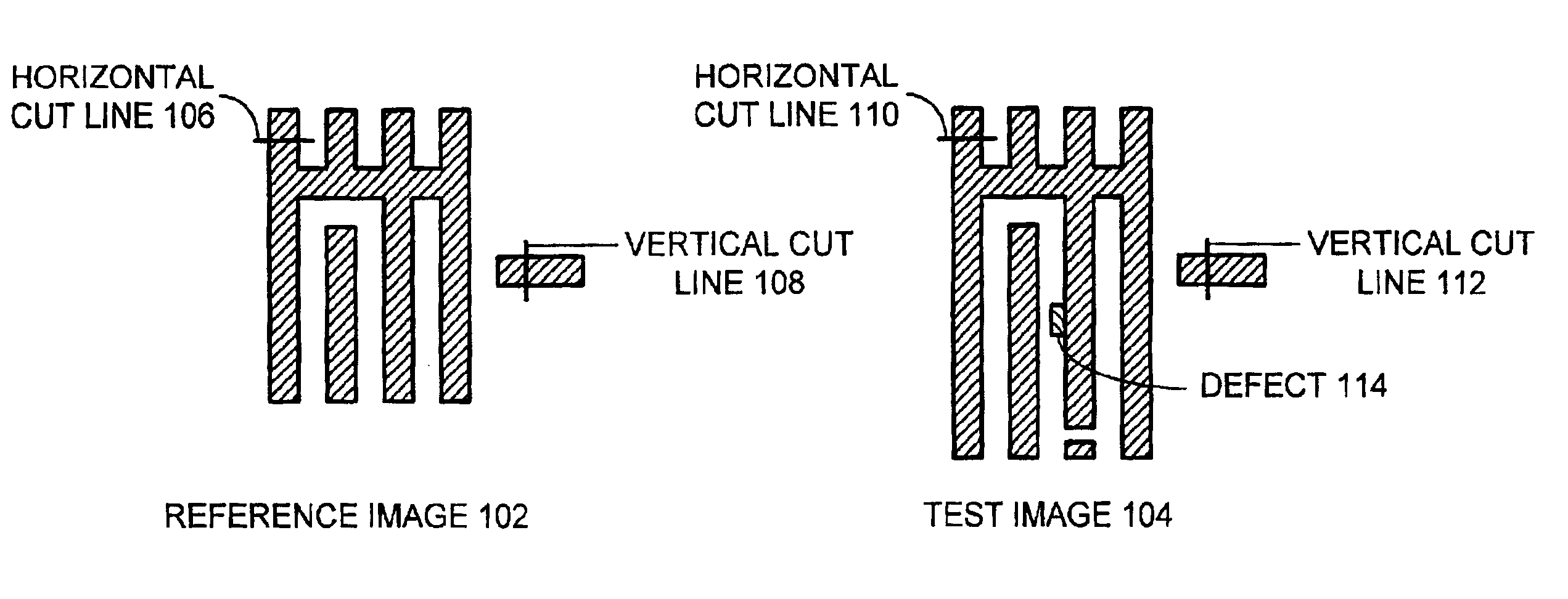
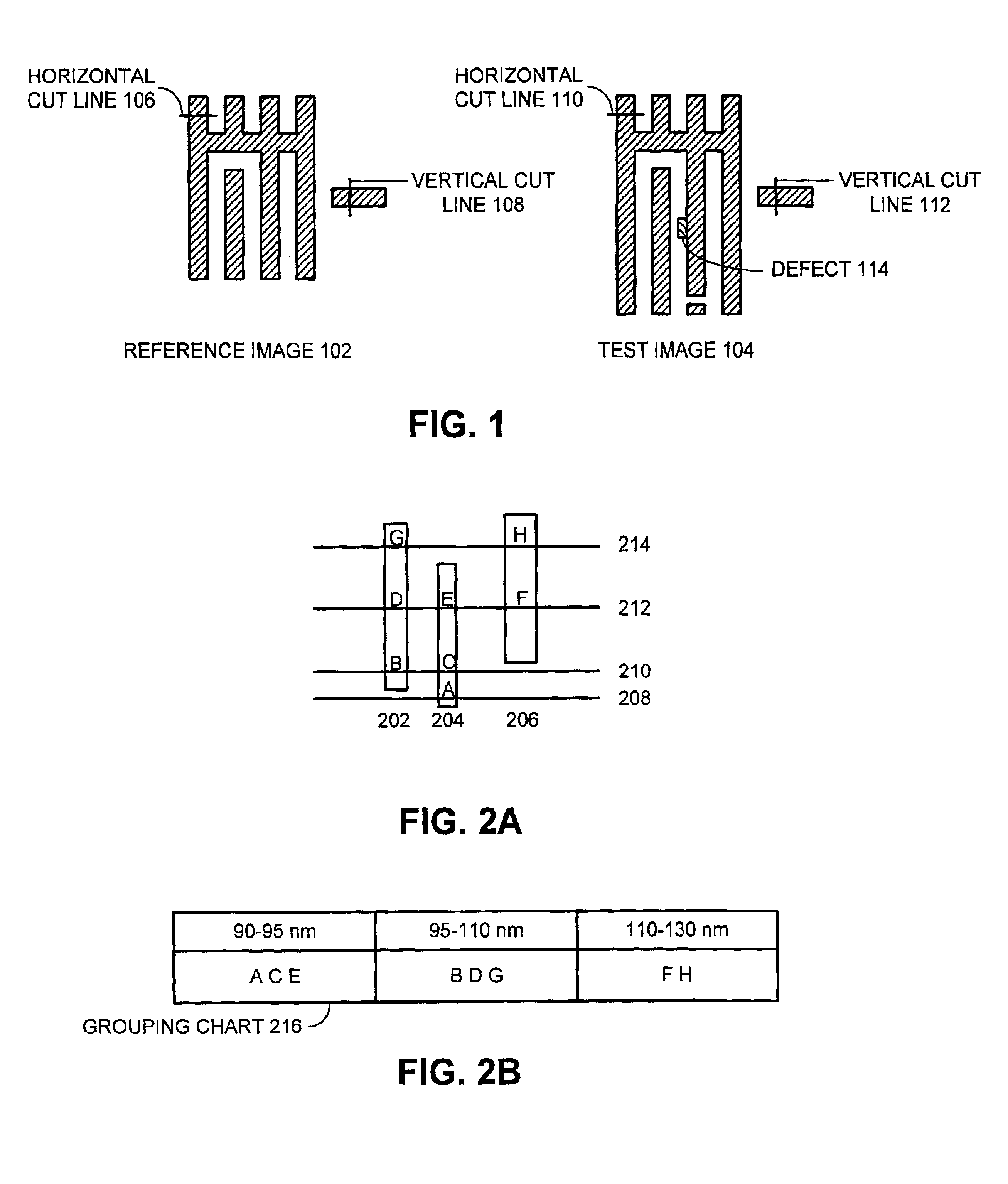
FIG. 1 illustrates integrated circuit images in accordance with an embodiment of the invention. Reference image 102 and test image 104 include the same features of an integrated circuit, however, their sizes may not be identical, as shown. Reference image 102 may be a computer-generated image generated from a GDS-II description or other system description of the layout, a mask image, or a wafer image used for comparison with test image 104. Test image 104 may also be a computer-generated image, a mask image, or a wafer image used for comparison with reference image 102, and may include defects such as defect 114.

In operation, the system places horizontal and vertical cut lines on reference image 102. FIG. 1 illustrates horizontal cut line 106 and vertical cut line 108 on reference image 102. The system also places horizontal and vertical cut lines on test image 104. FIG. 1 illustrates horizontal cut line 110 and vertical cut line 112 on test image 104. The s...


PUM


Abstract

One embodiment of the invention provides a system that facilitates auto-alignment of images for defect inspection and defect analysis. The system operates by first receiving a reference image and a test image. Next, the system creates a horizontal cut line across the reference image and chooses a vertical feature on the reference image with a specified width along the horizontal cut line. The system also creates a vertical cut line across the reference image and chooses a horizontal feature on the reference image with the specified width along the vertical cut line. Finally, the system locates the vertical feature and the horizontal feature on the test image so that the reference image and the test image can be aligned to perform defect inspection and defect analysis.

Description

BACKGROUND1. Field of the InventionThe invention relates to the process of inspecting integrated circuit images. More specifically, the invention relates to a method and an apparatus to facilitate auto-alignment of mask and die images of integrated circuits for defect inspection and / or defect analysis.2. Related ArtIntegrated circuits can be produced through an optical lithography process that involves creating a mask with a pattern specifying where the various features of the integrated circuit are to be placed and then passing radiation through the mask to expose the pattern on a semiconductor wafer. This pattern defines where the surface of the semiconductor wafer is to be etched or where new material is to be added to create the integrated circuit.As the features of an integrated circuit continue to get smaller, quality control becomes increasingly important in order to ensure that the integrated circuit functions properly. As part of this quality control, integrated circuit man...

Claims


Application Information

Patent Timeline
Patent Type & Authority Patents(United States)
IPC IPC(8): G06T7/00
CPCG06T7/001G06T7/0028G06T2207/30148G06T7/33
Inventor CAI, LYNN
Owner SYNOPSYS INC
Why Eureka
Try Eureka