Combined fuel injection valve/ignition plug

a fuel injection valve and fuel injection plug technology, which is applied in the direction of spark plugs, machines/engines, mechanical equipment, etc., can solve the problems of inability to meet the requirements of reliability, the so-called jet root of the fuel jet spray-discharged from the spray-discharge orifice cannot be reliably ignited with the required reliability, and the discharge orifice of the fuel jet may be subject to constant worsening

Inactive Publication Date: 2005-03-29
ROBERT BOSCH GMBH
View PDF17 Cites 61 Cited by
  • Summary
  • Abstract
  • Description
  • Claims
  • Application Information

AI Technical Summary

Benefits of technology

In contrast, the fuel injector-spark plug combination of the present invention has the advantage over the related art that by a biaxial arrangement of the valve needle of the fuel injector and the spark-plug insulator of the spark plug in a shared housing, which is insertable in the cylinder head of the internal combustion engine, the components are optimally arranged relative to each other, the system being easy to install and requiring little space.
Particularly advantageous is the tilting of the longitudinal axis of the spark-plug insulator relative to the longitudinal axis of the valve needle, since it is prevents that the spark plug is directly exposed to the fuel jet of the fuel injector.
The fact that the spark location may be brought up closer to the nozzle (compared to the parallel axis arrangement), constitutes an additional advantage since it allows an unthrottled idling operation.
Moreover, it is advantageous that the spark plug and the ground electrode of the spark plug are each exchangeable independently of the fuel injector.

Problems solved by technology

However, a disadvantage of the known fuel injector with integrated spark plug is that the location of the spark arc-over is not defined with respect to the fuel jet spray-discharged from the discharge orifice, since the spark arc-over may occur at just about any point in the lateral region of a projection of the valve body.
In this known design a reliable ignition of the so-called jet root of the fuel jet spray-discharged from the spray-discharge orifice is not possible with the required reliability.
Furthermore, the discharge orifice of the fuel jet may be subject to continually worsening carbon fouling or coking, which influences the shape of the spray-discharged jet.

Method used


Image

  • Combined fuel injection valve/ignition plug
  • Combined fuel injection valve/ignition plug
  • Combined fuel injection valve/ignition plug

Examples


Embodiment Construction

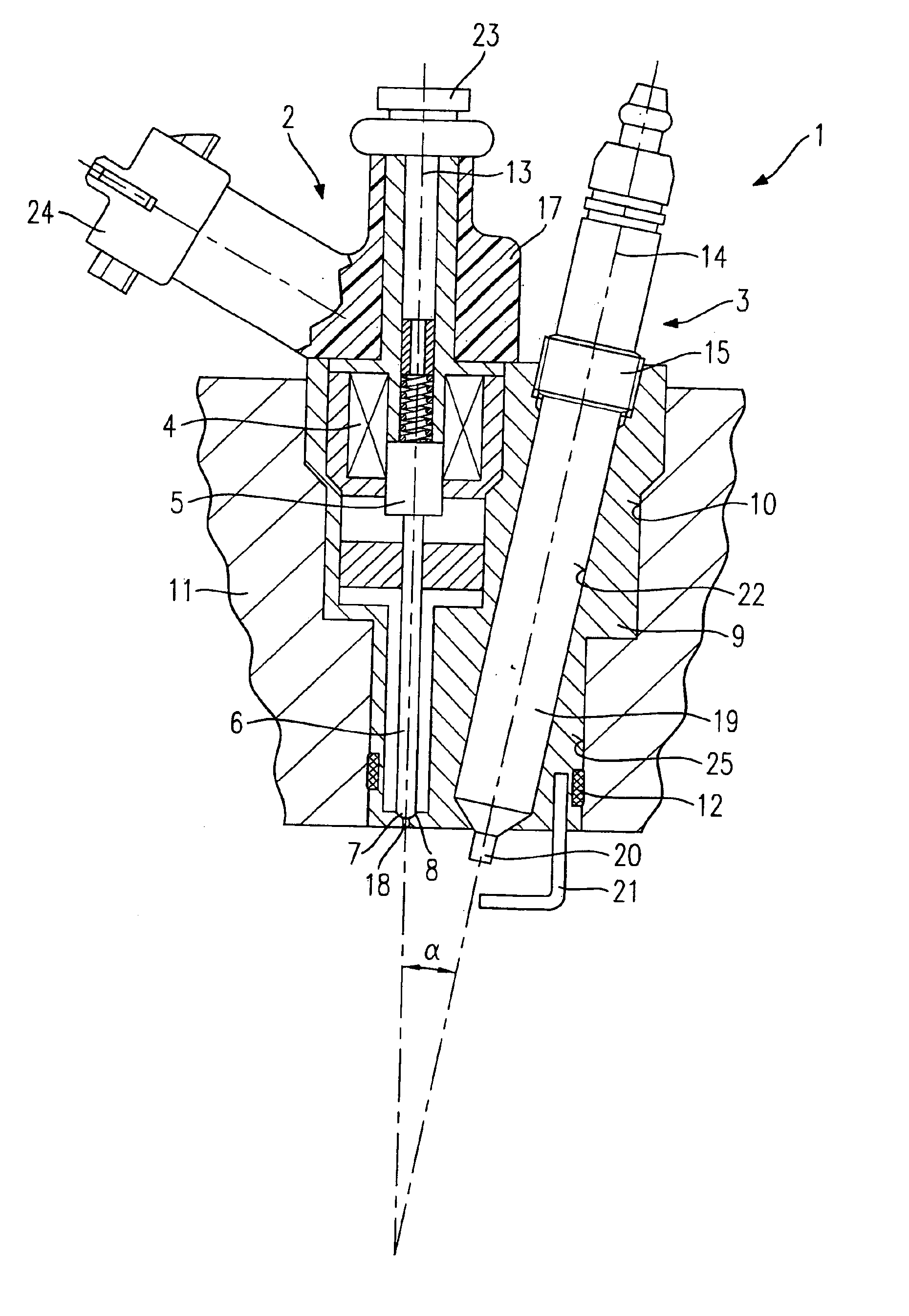
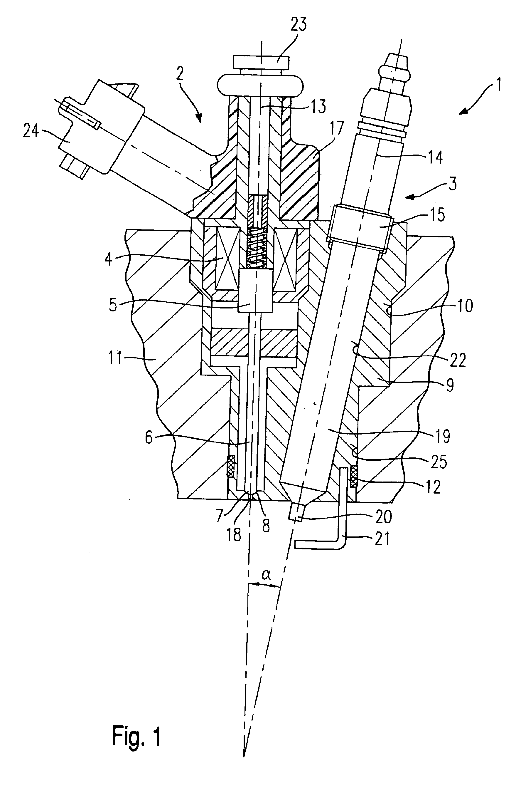
FIG. 1 shows a fuel injector-spark plug combination 1 including a fuel injector 2 for the direct injection of fuel into a combustion chamber of a mixture-compressing internal combustion engine having external ignition, and having a spark plug 3 for igniting the fuel spray-discharged into the combustion chamber, according to a first exemplary embodiment of the present invention.

Fuel injector 2 has an actuator 4, which is embodied in the form of a solenoid coil in the present exemplary embodiment. Actuator 4 cooperates with an actuation device 5 for a valve needle 6, the actuation device being embodied as a solenoid armature 5 which cooperates with solenoid coil 4 in the present exemplary embodiment. At its downstream-side end, valve needle 6 has a valve-closure member 7, which cooperates with a valve-seat surface 8 to form a sealing seat. Fuel injector 2 has at least one spray-discharge orifice 18 through which fuel is spray-discharged into the combustion chamber of the internal comb...


PUM


Abstract

A fuel injector-spark plug combination comprises a fuel injector for the direct injection of fuel into a combustion chamber of an internal combustion engine and a spark plug with a spark-plug insulator, a first electrode and a second electrode for igniting the fuel injected into the combustion chamber. The fuel injector includes an actuator cooperating with an actuation device, which is in force-locking, operative connection to a valve needle, the valve needle, or a valve-closure member connected thereto, cooperating with a valve-seat surface to form a sealing seat. The valve needle of the fuel injector and the spark-plug insulator of the spark plug are positioned in a shared housing at a biaxial offset.

Description

FIELD OF THE INVENTIONThe present invention is based on a fuel injector-spark plug combination.BACKGROUND INFORMATIONFrom the European Published Patent Application No. 0 661 446, a fuel injector having an integrated spark plug is known. The fuel injector with integrated spark plug is used for the direct injection of fuel into the combustion chamber of an internal combustion engine and for igniting the fuel injected into the combustion chamber. Due to the compact integration of a fuel injector with a spark plug, it is possible to save installation space at the cylinder head of the internal combustion engine. The known fuel injector with integrated spark plug has a valve body which, together with a valve-closure member able to be actuated by means of a valve needle, forms a sealing seat, adjacent to which is a spray-discharge orifice, which discharges at an end face of the valve body facing the combustion chamber. A ceramic insulation element insulates the valve body from a housing bo...

Claims


Application Information

Patent Timeline
Patent Type & Authority Patents(United States)
IPC IPC(8): F02M57/06F02M57/00F02M61/00F02M61/14F02M51/06F02P13/00H01T13/40
CPCF02M61/14F02M57/06F02M51/0671F02M2200/858
Inventor HERDEN, WERNERVOLZ, DIETERWUERFEL, GERNOTMELSHEIMER, ANJASCHMITTINGER, SIMONNORGAUER, RAINERDEPONTE, RENE
Owner ROBERT BOSCH GMBH
Why Eureka
Try Eureka