Slit tip ventricular catheter

Inactive Publication Date: 2005-03-29
INTEGRA LIFESCI
View PDF6 Cites 64 Cited by
  • Summary
  • Abstract
  • Description
  • Claims
  • Application Information

AI Technical Summary

Benefits of technology

The present invention is directed to an improved slit tip ventricular catheter that is constructed and packaged in a manner to prevent the slit tip from knitting or the edges adhering together during sterilization or storage. The present invention accomplishes this desirable result by inserting a thin inert tab into the

Problems solved by technology

One of the difficulties in the use of slit catheters is the tendency of the edges of the catheter adjacent the slit be adhered together or knit together duri

Method used


Image

  • Slit tip ventricular catheter
  • Slit tip ventricular catheter
  • Slit tip ventricular catheter

Examples


Embodiment Construction

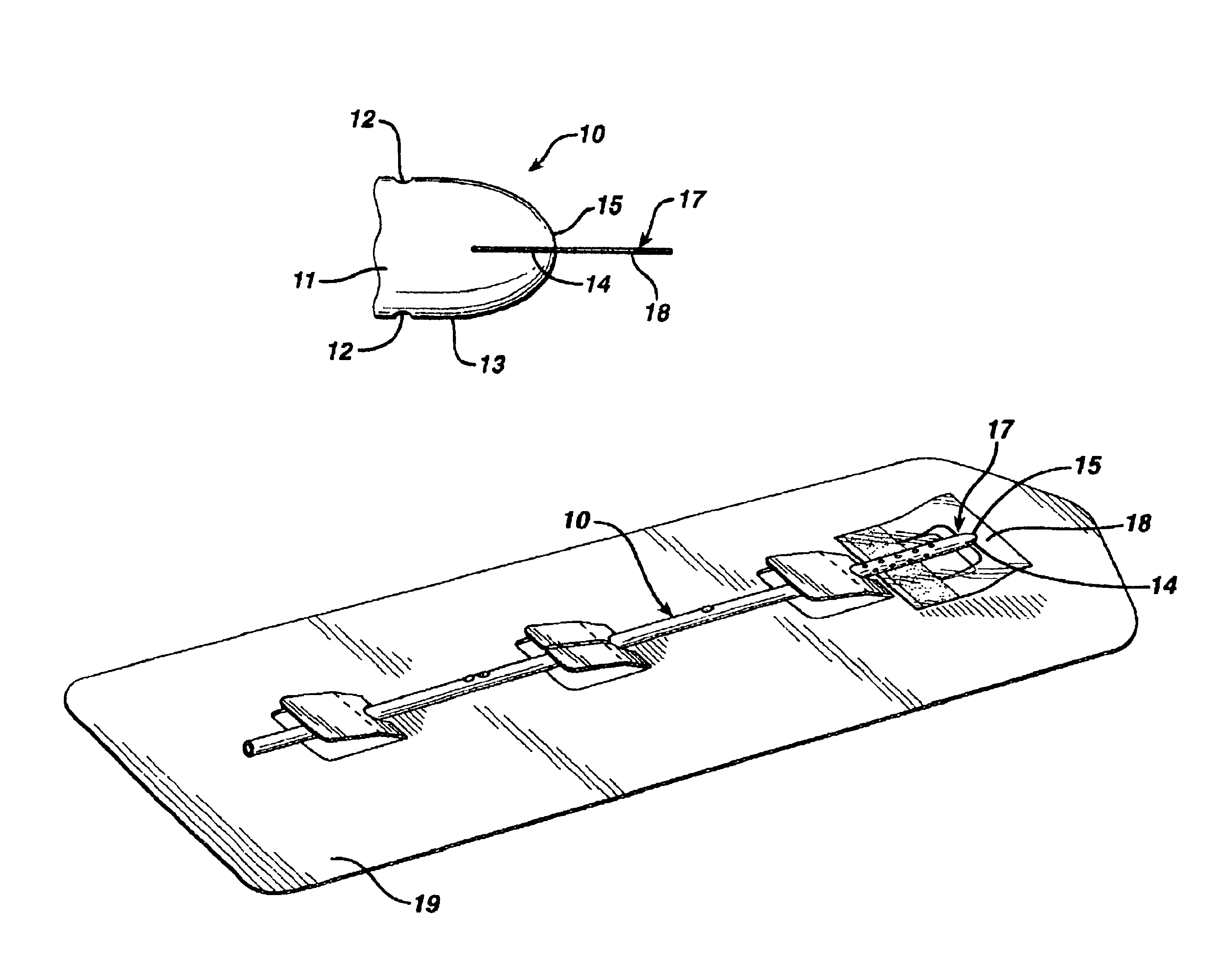
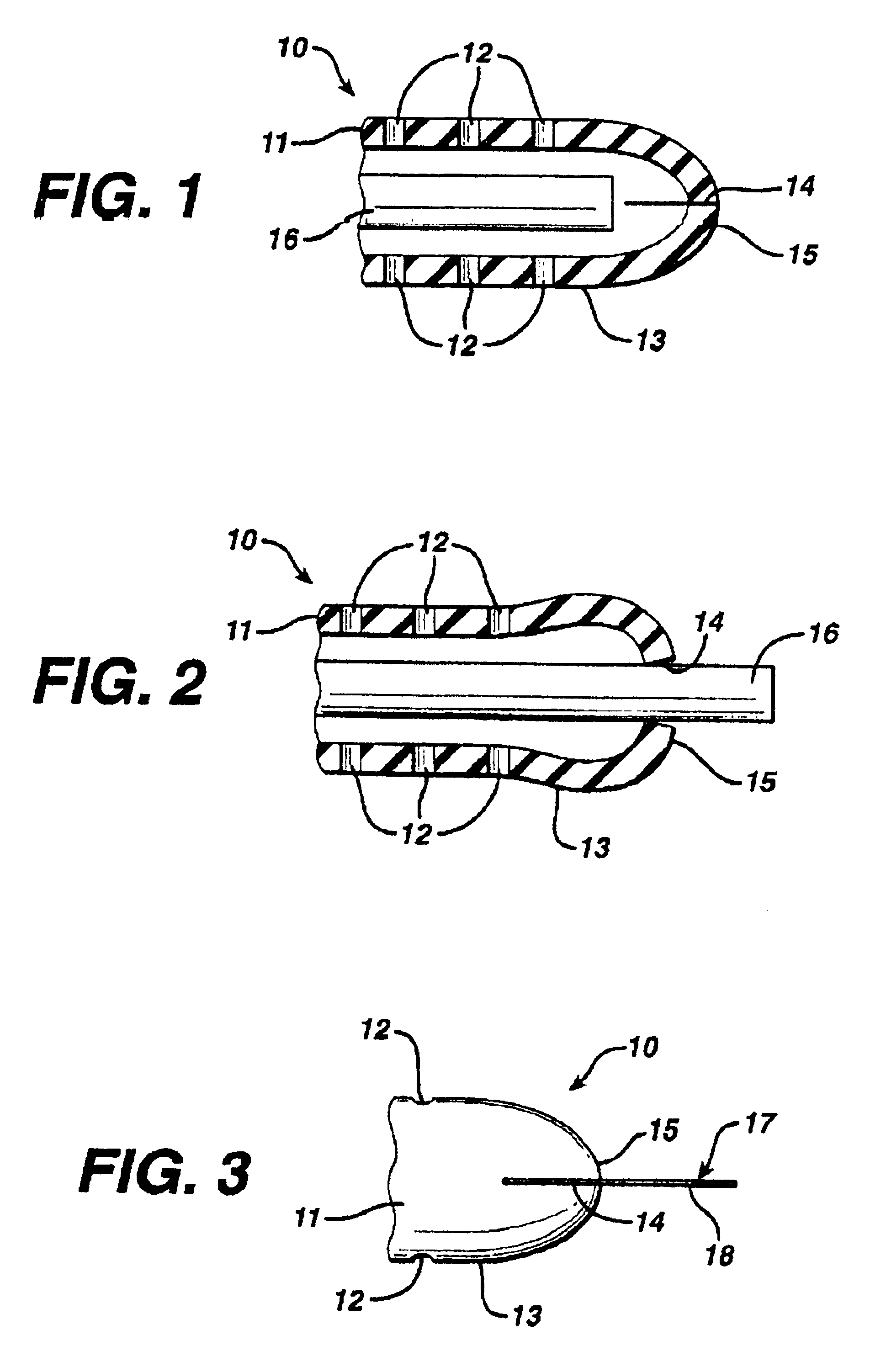
As shown in FIG. 1, a slit tip ventricular catheter 10 has a tubular body 11 and a number of fluid flow apertures 12 in the distal portion 13 of the tubular body. There is a slit 14 in the distal tip 15 of the catheter.

As shown in FIG. 2, if a stylet or optical endoscope 16 is pushed against the slit 14, the slit will open to allow the stylet or optical endoscope to pass through the distal tip catheter to aid in positioning the catheter.

Ventricular catheters are commonly constructed of a biologically compatible plastic material such as a silicone elastomer, commonly referred to as sliastic. The opposed edges of the slit at the distal end of the catheter are in contact with each other during sterilization and subsequent storage until use. The opposed edges of the slit have a tendency to adhere to each other or knit together. When this knitting occurs, it is difficult and sometimes impossible to force a stylet or optical endoscope through the slit. The catheter must then be removed fr...


PUM


Abstract

A ventricular catheter of the type having a slit in the distal end to permit the passage of a stylet or endoscope is disclosed. The catheter is packaged with a film tab inserted into the slit to prevent the edges of the slit from knitting or adhering to each other upon sterilization or storage.

Description

This invention is directed to an improvement in a ventricular catheter to prevent a slit at the distal end of the catheter from adhering together or knitting during sterilization or storage.BACKGROUND OF THE INVENTIONVentricular catheters are widely used in various procedures including the collection of cerebrospinal fluid, introduction of contrast medium or chemotherapy, the measurement of intracranial pressure and the treatment of hydrocephalus. The proper positioning of the catheter in the ventricular system is facilitated by the use of a rigid stylet or the use of an optical endoscope.The catheters are generally constructed of silicone elastomer tubing and have a series of fluid flow apertures adjacent the distal end and a slit at the distal end. The slit is capable of opening to permit the terminal end of a stylet or optical endoscope to pass through the slit to properly position the catheter. When the catheter is in the desired position in the ventricle, the stylet or optical ...

Claims


Application Information

Patent Timeline
IPC IPC(8): B65D83/08B65D83/10A61M25/00
CPCA61M25/0075A61M25/002
Inventor CAO, HONGHOA
Owner INTEGRA LIFESCI
Why Eureka
Try Eureka