Air bag module diffuser

a technology of airbag module and diffuser, which is applied in the direction of pedestrian/occupant safety arrangement, vehicular safety arrangement, vehicle components, etc., can solve the problems of reducing the ability of the vent hole to expand the airbag, reducing the ability of the vent hole to distribute air flow, and reducing the ability of the airbag to expand. , the effect of reducing heat loss and reducing temperature loss

Inactive Publication Date: 2005-03-29
KEY SAFETY SYST
View PDF8 Cites 20 Cited by
  • Summary
  • Abstract
  • Description
  • Claims
  • Application Information

AI Technical Summary

Benefits of technology

The present invention comprises an air bag module, having an air bag and air bag inflator. The air bag has an interior cavity and an air bag opening leading into the interior cavity. In the event of air bag deployment, the air bag inflator discharges an inflation gas out of an outlet generally to the side of the vehicle occupant. A vane then redirects the flow of inflation gas so that the air bag may deploy toward the vehicle occupant. In contrast to existing air bag modules, however, the vane of the inventive air bag module extends from the air bag opening into the interior cavity of the air bag. In this way, the vane is located completely within the insulating confines of the air bag. This unique location for the vane reduces heat loss significantly. Accordingly, the vane allows the inflation gas to maintain its high temperature within the air bag while still redirecting the air bag towards the vehicle occupant.
The vane is located near the air bag opening. Moreover, to further reduce temperature loss, the vane is sized smaller than the air bag opening. The vane may have a dimension, such as a width, less than a dimension of the air bag opening, such as an opening width. By reducing the size of the vane relative to the air bag opening, the high temperature of the inflation gas is further maintained.
A support may be used to hold the vanes in place relative to the air bag. The support may comprise a number of vanes each spaced next to an air bag opening. To reduce heat loss, the air bag may be attached around the support. The support may be rectangular in shape. In addition, pressure relief holes may be provided in the support to adjust the distribution of inflation gas across the air bag opening.
The invention further encompasses an inventive manufacturing technique. A vane is placed next to an air bag opening on a support. Rather than placing the vane outside of the air bag, the vane is extended into the air bag. The air bag is then attached around the support. This technique thus permits inflation gas to be directed toward the vehicle occupant without a significant loss of heat.

Problems solved by technology

However, challenges arise in the design of an air bag module for a passenger side air bag.
Vent holes are not very effective in redistributing air flow.
Applicant has discovered that these vanes draw heat away from the inflation gas and consequently reduce its ability to expand the air bag.

Method used


Image

  • Air bag module diffuser
  • Air bag module diffuser
  • Air bag module diffuser

Examples


Embodiment Construction

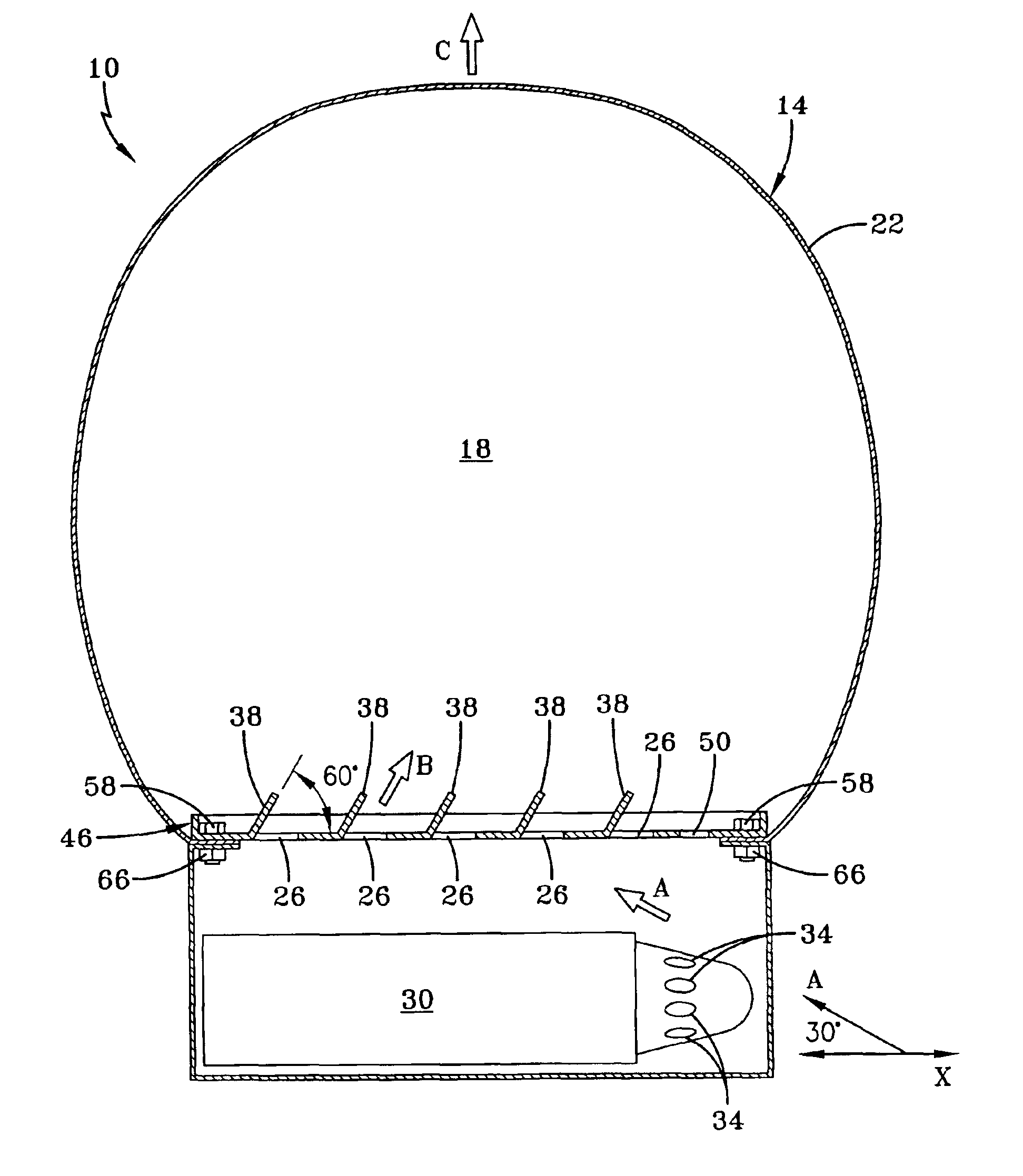
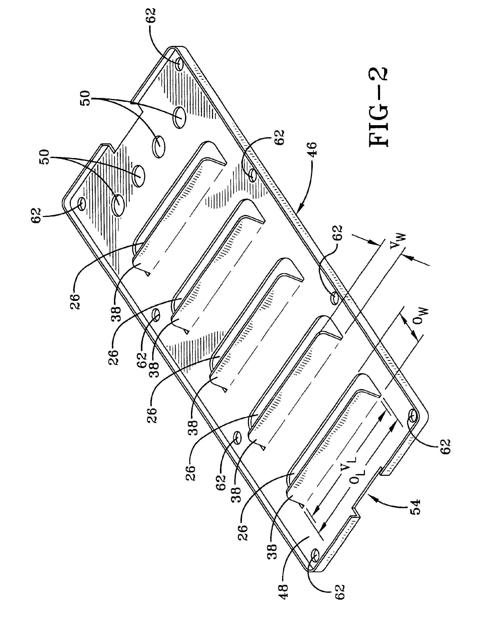
FIG. 1 illustrates inventive air bag module 10 comprising air bag 14 and air bag inflator 30. Like existing air bag modules, air bag 14 has an exterior surface 22 that defines an interior cavity 18. Moreover, air bag inflator 30 has outlets 34, which, during deployment, direct inflation gas along the direction of path A. Path A may be at a 30° angle to an axis of inflator 30, axis X. Without guide structures, air bag 18 would tend to deploy generally along the direction of path A.

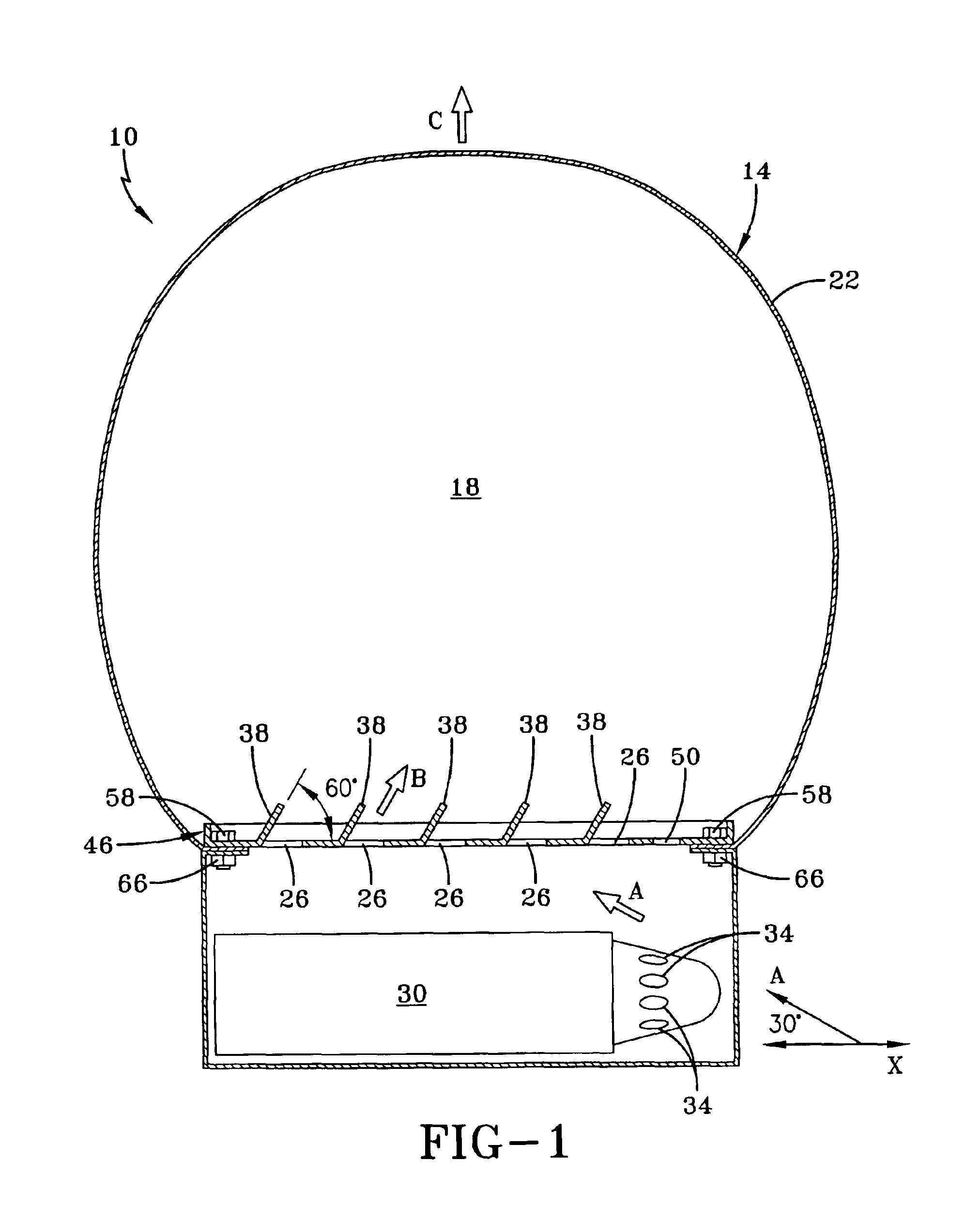
To address this issue, air bag module 10 has support 46 to redirect the flow of inflation gas from air bag inflator 30. Air bag support 46 has air bag openings 26 that permit the passage of inflation gas into interior cavity 18 from outlets 34 of air bag inflator 30. In addition, support 46 has vanes 38 that extend at an angle relative to support 46 as shown. The disclosed angle is approximately 60° or a 120° angle relative to axis X. As further shown in FIG. 1, each vane 38 is located adjacent each air bag...


PUM


Abstract

An air bag module comprises an air bag having an interior cavity. The air bag has an air bag opening in communication with the interior cavity. The air bag module has an air bag inflator with an outlet for inflating the air bag. At least one vane extends from the air bag opening into the interior cavity of the air bag.

Description

BACKGROUND OF THE INVENTIONThis invention relates to a passenger side air bag module.An air bag module typically comprises an air bag and an air bag inflator. When a severe crash is detected by a vehicle's crash detection system, the system may instruct the air bag module to deploy. If this event occurs, the air bag inflator rapidly discharges an inflation gas at a very high temperature into the air bag. The high temperature of the gas causes its rapid expansion, thereby inflating the air bag to form a cushion against vehicle impact for a vehicle occupant. Preferably, the air bag should deploy towards the vehicle occupant to maximize cushioning. However, challenges arise in the design of an air bag module for a passenger side air bag. Specifically, due to the shape of passenger side air bag inflators, inflation gas from the air bag inflator may discharge toward the side of the vehicle occupant. As a consequence, the air bag may deploy toward the side of the vehicle occupant rather t...

Claims


Application Information

Patent Timeline
Patent Type & Authority Patents(United States)
IPC IPC(8): B60R21/20B60R21/26B60R21/217
CPCB60R21/261B60R21/2171
Inventor THOMAS, DAVID E.
Owner KEY SAFETY SYST
Why Eureka
Try Eureka