Cable terminating apparatus and method

Active Publication Date: 2005-03-29
COMMSCOPE CONNECTIVITY SPAIN
View PDF6 Cites 23 Cited by
  • Summary
  • Abstract
  • Description
  • Claims
  • Application Information

AI Technical Summary

Benefits of technology

It is, therefore, an object of the invention to provide a method and device that facilitates the termination of a cable having a plurality of wires with a connector having a plurality of terminals. It is another object of the invention to provide a method and device that cuts wire ends proximate to terminals of the connector in a convenient manner and ensures that the wire ends are removed from the connector in such a way that the wire ends do not protrude from the connector and impede the application of a strain relief member to the connector. It is still a further object of the invention to provide a method and device that inserts the wires into terminals of the connector to a uniform controlled depth.

Problems solved by technology

This conventional method of termination, however, is difficult to perform and has several drawbacks, particularly in instances where the cable contains a significant number of small diameter wires.
Additionally, because the tools are made of plastic, the tools are not durable.

Method used


Image

  • Cable terminating apparatus and method
  • Cable terminating apparatus and method
  • Cable terminating apparatus and method

Examples


Embodiment Construction

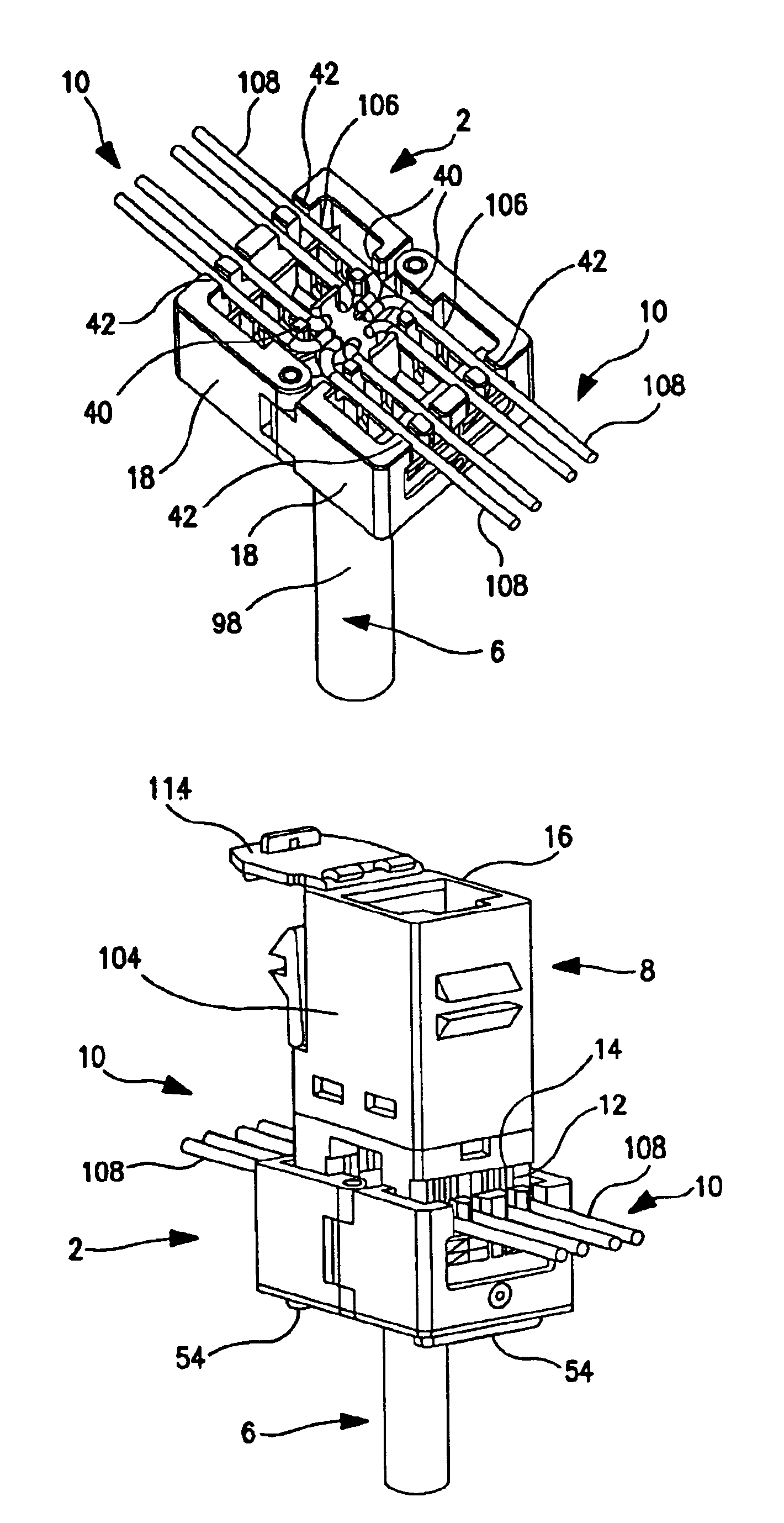
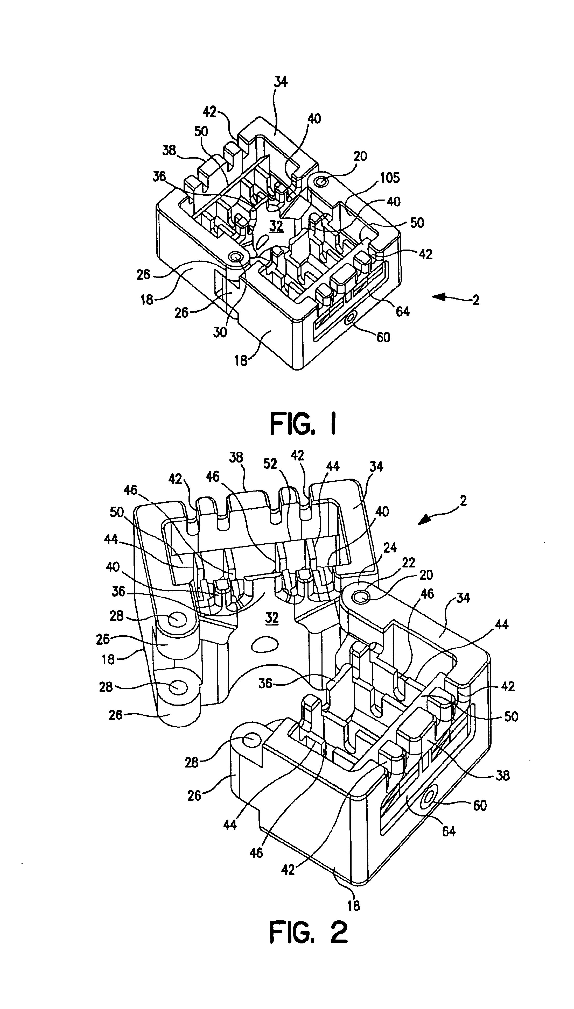
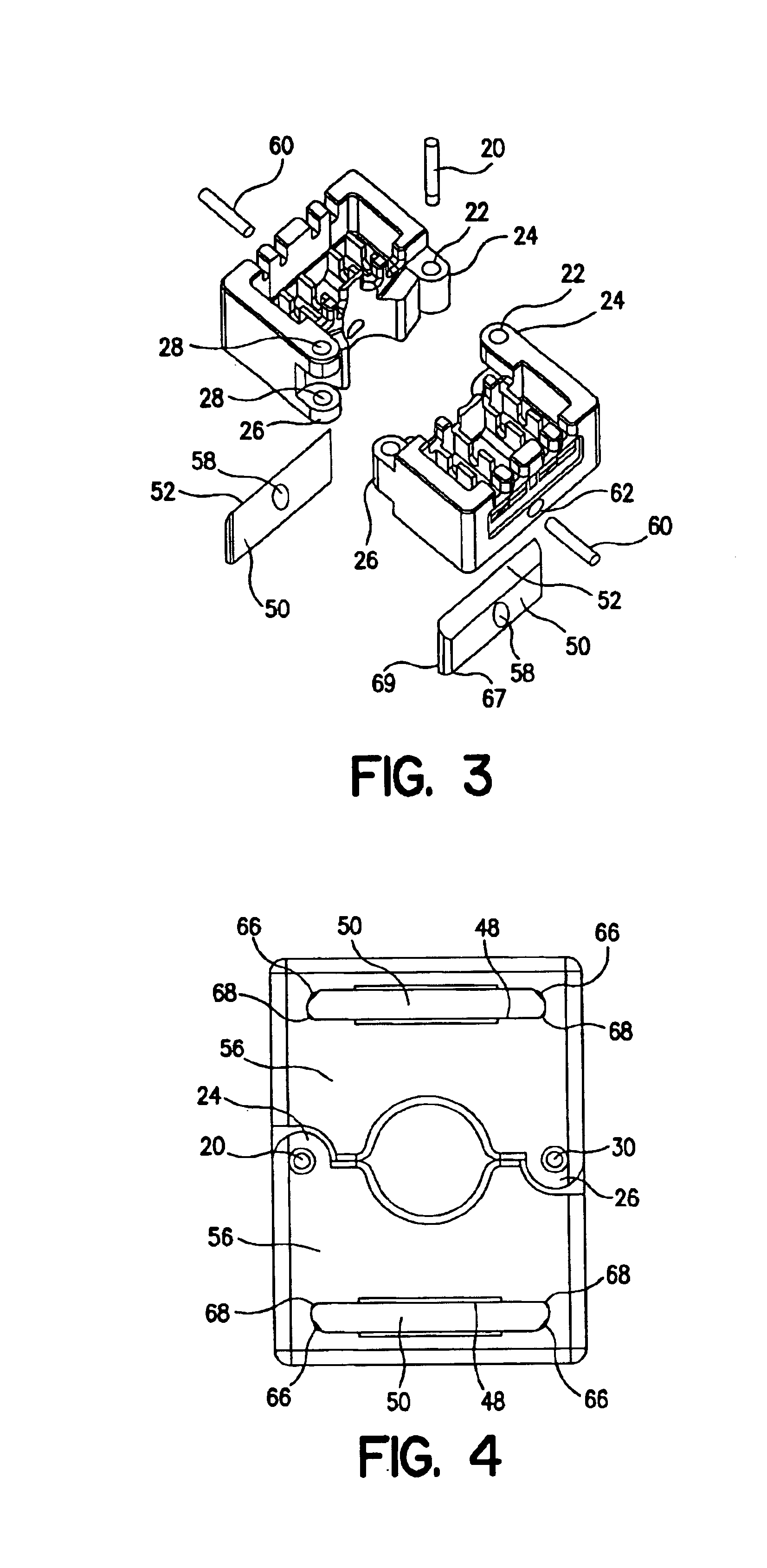
FIG. 9 shows a cable terminating apparatus according to the invention. The apparatus includes a cable holding device 2 and a squeezing tool 4 for terminating a cable 6 with a connector 8. As shown in FIGS. 1 and 2, the cable holding device 2 may be formed from metal and includes a housing having first and second housing parts 18. Hinge lugs 24 project from the first and second housing parts 18. Each of the hinge lugs 24 has a through-hole 22. The through-holes 22 are aligned for receipt of a pivot pin 20 to hingeably mount the first housing part 18 to the second housing part 18 such that the first and second housing parts 18 may be rotated between an open position shown in FIG. 2 and a closed position shown in FIG. 1. Locking lugs 26 are formed on a side opposite from the hinge lugs 24. Each of the locking lugs 26 has a through-hole 28. The through-holes 28 are aligned for receipt of a locking pin 30 that secures the first and second housing parts 2 in the closed position.

Between th...


PUM


Abstract

A cable terminating apparatus for terminating a cable having a plurality of wires with a connector, the cable terminating apparatus includes a housing having a plurality of slots arranged for positioning the plurality of wires in a fixed spaced relationship relative to each other. A connector has a plurality of terminals corresponding to the plurality of wires. A squeezing tool has a recess configured for receiving the housing and the connector. The squeezing tool has a moveable plate for urging the connector and the housing against a support wall and into engagement with each other to electrically connect the plurality of terminals with the plurality of wires.

Description

FIELD OF THE INVENTIONThe invention relates to an apparatus and method for terminating an electrical cable with a connector.BACKGROUND OF THE INVENTIONTo terminate a cable containing a plurality of wires with a connector containing a plurality of terminals, such as, a cable used for telecommunication applications, each of the wires is inserted one at a time into each of the terminals with a tool made of plastic. The wires are then pressed into engagement with the terminals and free ends of the wires are removed with a tool, such as pliers. This conventional method of termination, however, is difficult to perform and has several drawbacks, particularly in instances where the cable contains a significant number of small diameter wires. For example, the method of cutting the free ends of the wires with pliers results in the free ends having variable lengths. Because the length of the free ends is inconsistent, the free ends may come into contact with a metal shielding member. Additiona...

Claims


Application Information

Patent Timeline
IPC IPC(8): H01R43/01
CPCH01R4/2433H01R43/015H01R4/245
Inventor DE DIOS MARTIN, LONGINOS
Owner COMMSCOPE CONNECTIVITY SPAIN
Why Eureka
Try Eureka