
User interface

a user interface and user technology, applied in the field of user interfaces, can solve the problems of large display large number of input keys, and achieve the effects of reducing the size of electronic input devices, reducing the opening of devices, and increasing the distance between microphones and speakers

Inactive Publication Date: 2005-03-29
CORE WIRELESS LICENSING R L
View PDF25 Cites 16 Cited by
  • Summary
  • Abstract
  • Description
  • Claims
  • Application Information

AI Technical Summary

Benefits of technology

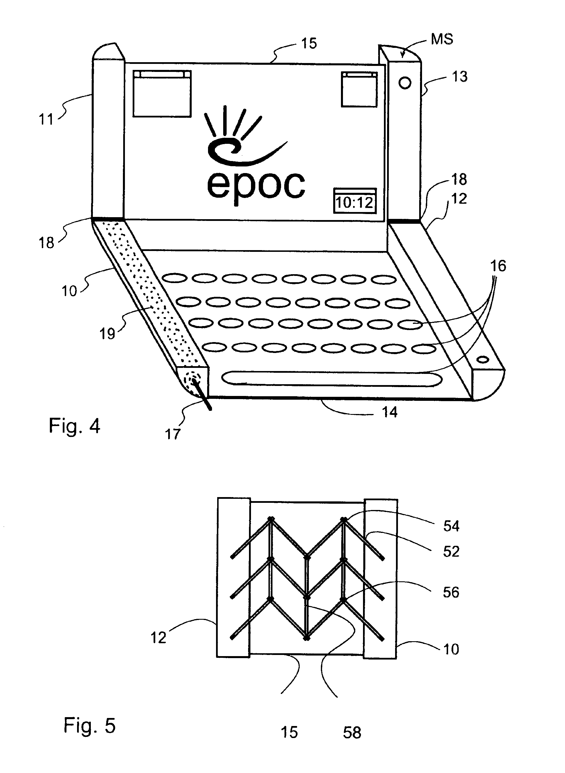
Now a user interface for an electronic input device has been invented, which input device has an input means extractable from a storage space of the device into an extended state and retractable back into the storage space into a retracted state. Thus, the size of the data input device can conveniently be made smaller for transport whilst the input means is protected in the storage space. The electronic input device can subsequently be put into a larger size when the input means is to be used.
Preferably, the electronic input device further comprises:a stop to prevent the device being opened beyond a certain maximum opening angle, anda means for changing the maximum opening angle when the configuration of the device is changed between the compacted spatial configuration and the extended spatial configuration. This provides different maximum opening angles for when the device is to be used in a telephone mode and when it is to be used in a data terminal mode. For example, it is possible to reduce the opening of the device to a convenient viewing angle for the data terminal mode. In the telephone mode, the mobile station can be further opened to increase the distance of the microphone and the speaker from each other.

Problems solved by technology

Consequently, electronic input devices generally require a relatively large display and a large number of input keys.
There is thus a conflict between the need to have a large display and a large keyboard to allow ease of use and the need to have a small portable electronic input device.
However, user interfaces of newer and more complicated devices, such as mobile telephones and Personal Digital Assistants, often have a computer-like functionality, and so require a display which is capable of displaying text (having a number of rows) and graphics.

Method used


Image

  • User interface
  • User interface
  • User interface

Examples


Embodiment Construction

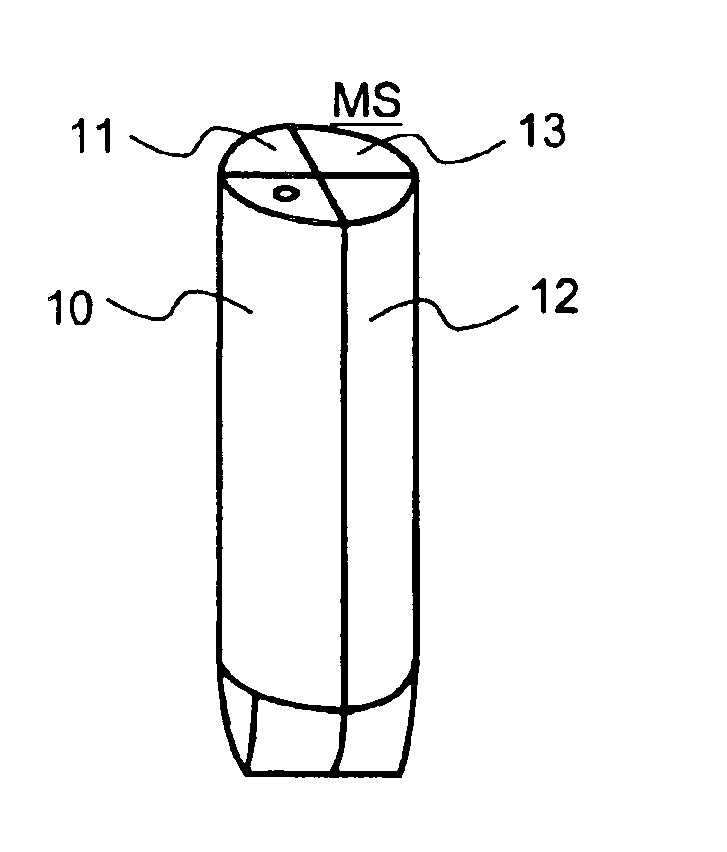
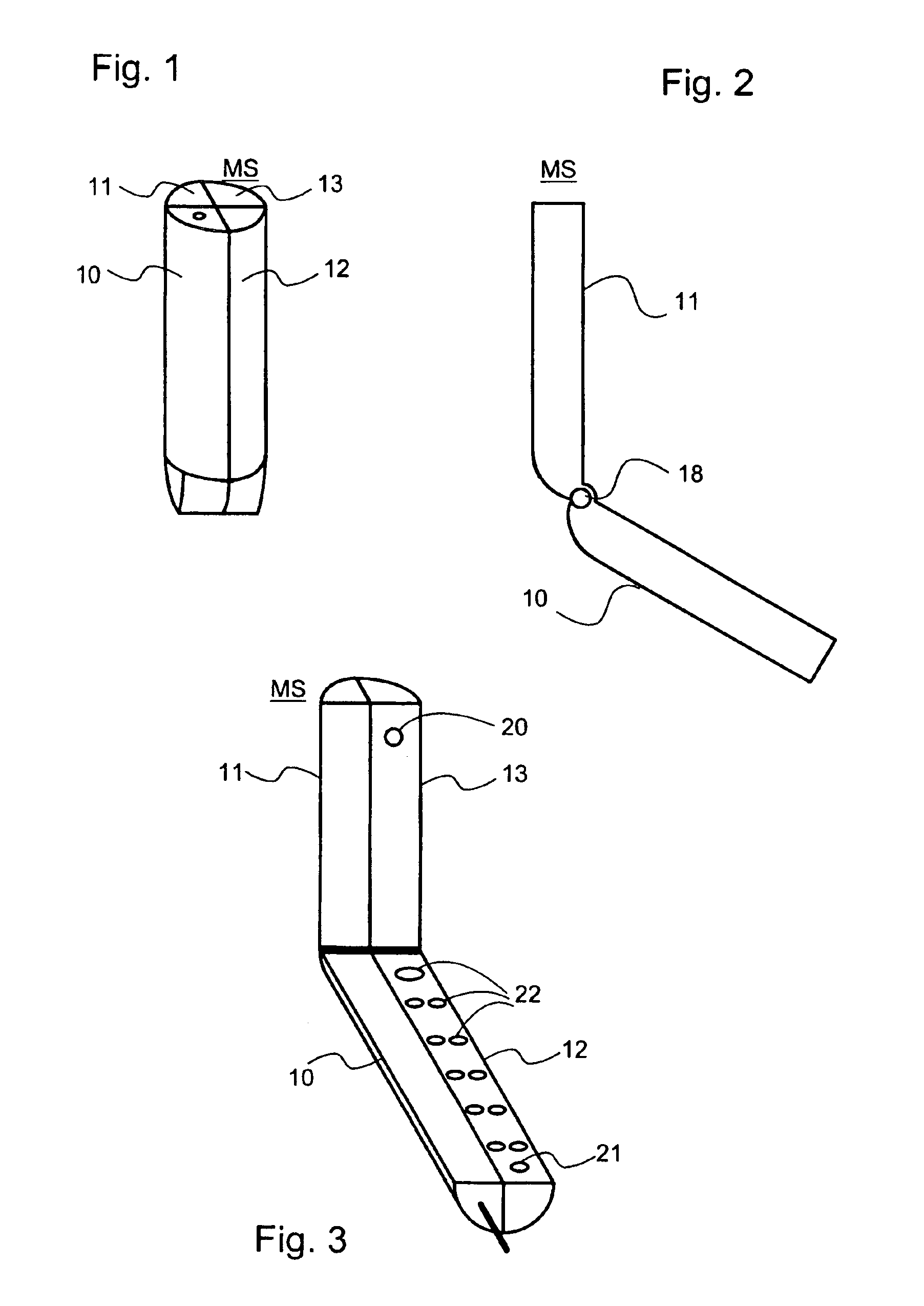
FIG. 1 shows a mobile station MS in a retracted configuration, which is suitable for transportation and to be carried by a user, for example in a pocket. It can be seen that in this retracted, or folded-up, configuration the mobile station is basically of a cylindrical shape. The mobile station comprises four elements 10, 11, 12, and 13, which have outwardly facing curved surfaces defining the cylindrical shape. The elements are a lower storage element 10, an upper storage element 11, a battery element 12 and an electronics housing element 13. The battery element 12 contains a battery for operating the mobile station. The electronics housing element 13 contains mobile station electronics to enable the mobile station to be used as, among other things, a mobile telephone and as a data terminal.

Referring now to FIGS. 2 and 3 it can be seen that elements 11 and 10 and elements 13 and 12 are hinged together with hinges 18. The elements 10 and 12 are adjacent to each other and form a firs...


PUM


Abstract

An electronic input device (MS) has a flexible keyboard (14) for receiving user input and a housing (10) defining a space for accommodating the keyboard. The input device has a compacted state and an extended state. The keyboard adopts a compacted spatial configuration in the compacted state and adopts an extended spatial configuration in the second state. In the compacted state the keyboard is wound on a roll. The input device additionally has a retractable, flexible display having corresponding compacted and extended states so that both the keyboard and the display can be rolled in and out together.

Description

FIELD OF THE INVENTIONThe invention relates to user interfaces, and relates especially to minimising the size of user interfaces.BACKGROUND OF THE INVENTIONDuring the last two decades different types of small electronic input devices have been developed, especially for mobile telecommunication. These devices generally have a keypad comprising either a set of buttons typically used on a telephone handset or a small keyboard in the QWERTY format.It is common in such electronic input devices to provide a display to let a user see information which has been entered via the keypad or keyboard and to provide the user with other information such as received messages, instructions or other information. Developments in electronic and battery technologies have allowed manufacture of ever smaller devices having ever greater functionality. This improvement in functionality has enabled users to interact with electronic input devices in more ways, which has led to more menu options being availabl...

Claims


Application Information

Patent Timeline
IPC IPC(8): G06F1/16G09F9/30H04M1/02H04M1/23
CPCG06F1/1615G06F1/1652G06F1/1656G06F1/1666G06F1/1679G09F9/301H04M1/0247H04M1/0268H04M1/23G09F9/30H04M1/0214H04M1/0235
Inventor HEMIA, TEPPOHIETAMAKI, JOUNIMERILAHTI, MIIKKAMURTONIEMI, MIRKANOUSIAINEN, JUHA
Owner CORE WIRELESS LICENSING R L
Learn More