Flat display panels and having a ventilation duct secured to a back substrate via a sealing member, and methods of manufacturing the same

a technology of flat display panels and sealing members, which is applied in the direction of tubes with screens, gas exhaustion means, instruments, etc., can solve the problems of producing scratches or stains on the front glass substrate, and achieve the effect of no scratches or stains

Inactive Publication Date: 2005-03-29
PIONEER CORP +1
View PDF5 Cites 7 Cited by
  • Summary
  • Abstract
  • Description
  • Claims
  • Application Information

AI Technical Summary

Benefits of technology

It is therefore a first object of the present invention to provide a flat display panel capable of being manufactured without giving scratches or stains on a display screen of the panel and also having a ventilation duct completely sealed thereto.
It is a second object of the present invention to provide a method of manufacturing flat display panels which is capable of attaching a ventilation duct with complete sealing and further with giving no scratches or stains on a display screen of the panel.

Problems solved by technology

However, the fact that the front glass substrate 1 is placed so that its front surface points downward and supported by the supported arms M in the process of mounting the ventilation duct 4 on the back glass substrate 2 as done in the foregoing conventional manufacturing method, gives rise to the problem of producing scratches or stains on the front glass substrate 1 which serves as the display screen for images.

Method used


Image

  • Flat display panels and having a ventilation duct secured to a back substrate via a sealing member, and methods of manufacturing the same
  • Flat display panels and having a ventilation duct secured to a back substrate via a sealing member, and methods of manufacturing the same
  • Flat display panels and having a ventilation duct secured to a back substrate via a sealing member, and methods of manufacturing the same

Examples


Embodiment Construction

A preferred embodiment according to the present invention will be described hereinafter in detail with reference to the accompanying drawings.

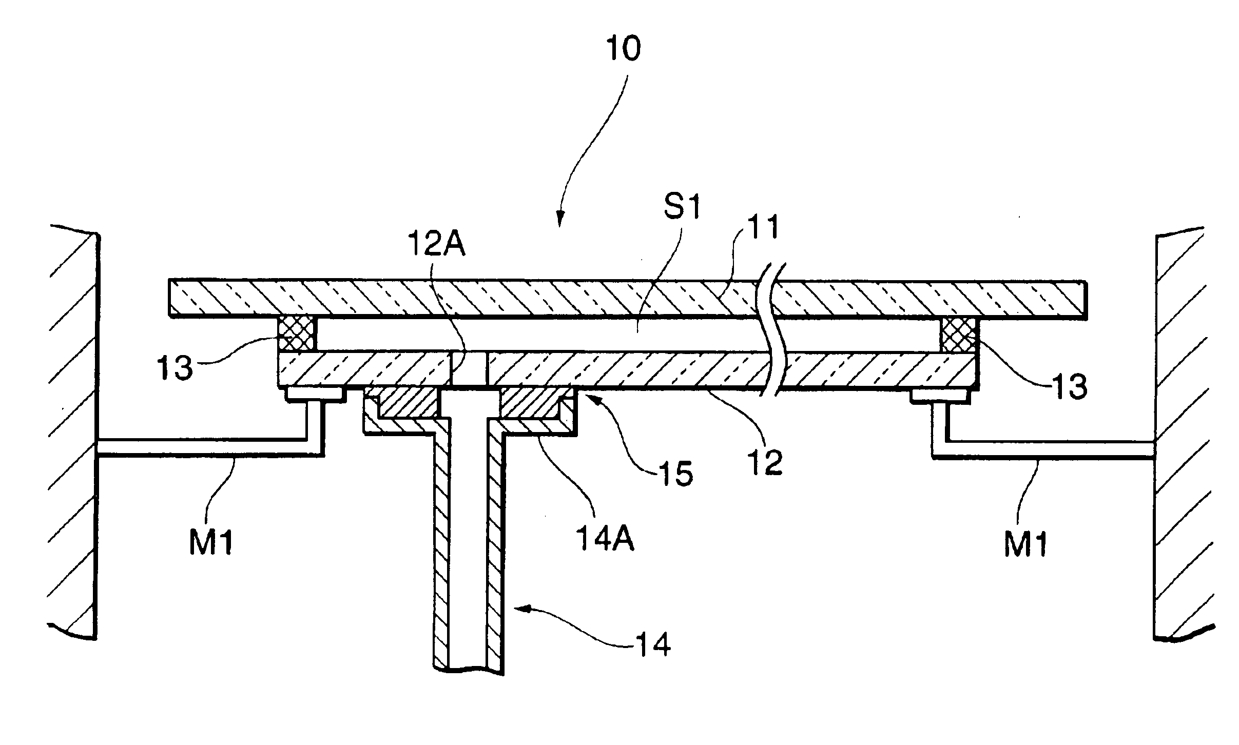
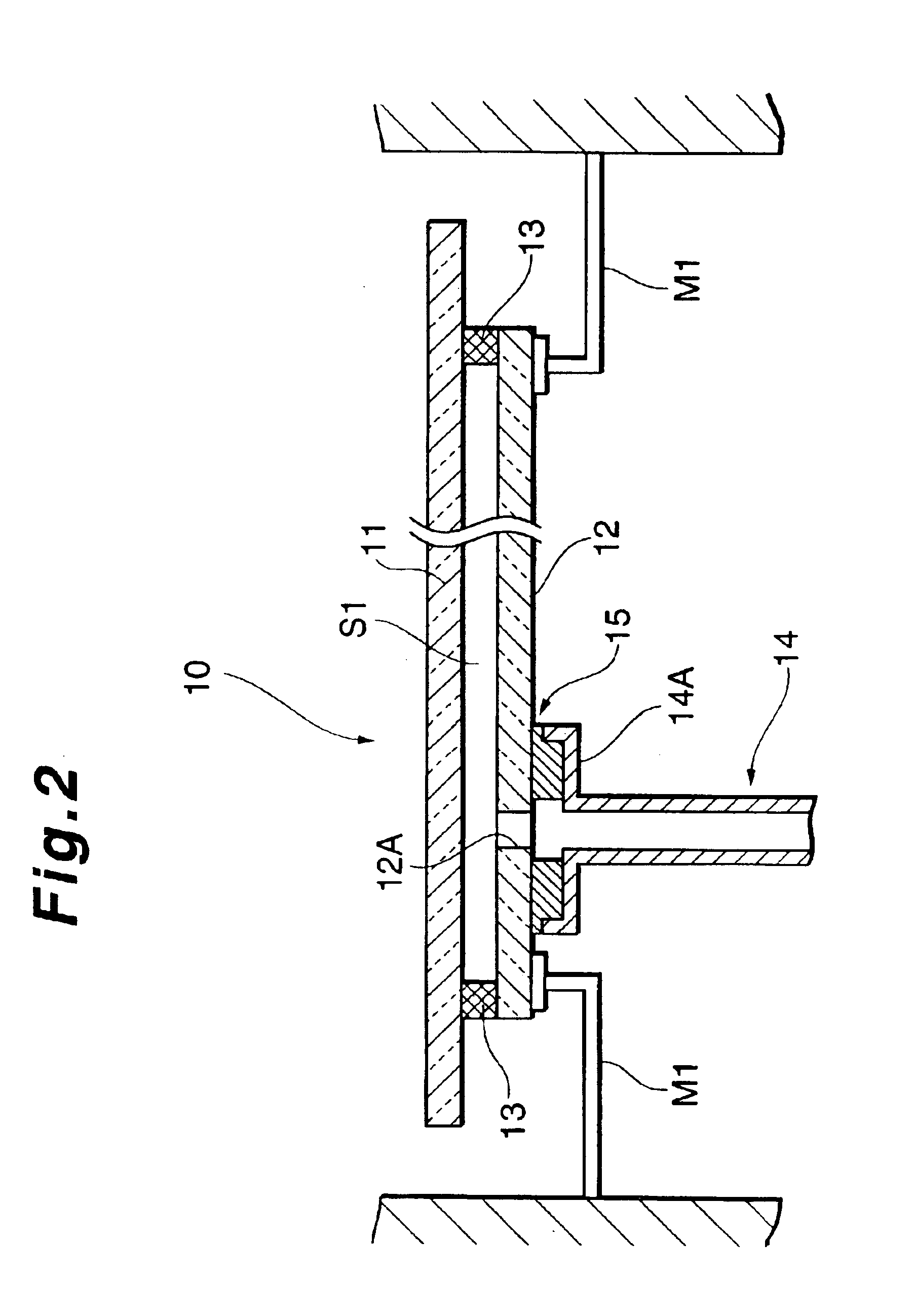
FIG. 2 is a sectional side view illustrating a flat display panel under the manufacturing process in an embodiment according to the present invention.

In FIG. 2, a flat display panel 10 such as a plasma display panel (PDP), a field emission display (FED) panel, or the like has a front glass substrate 11 and a back glass substrate 12 facing each other at a predetermined interval. A space S1 thus defined between the glass substrates 11 and 12 is sealed by a sealing layer 13 formed on the peripheral edge between the front glass substrate 11 and the back glass substrate 12.

A ventilation hole 12A is formed in the inner portion of the back glass substrate 12 close to the sealing layer 13 and opposite the non-display area, and establishes communication between the space S1 and the outside.

A ventilation duct 14 is mounted on the back glass substrate 12...


PUM


Abstract

A flat display panel has a ventilation hole formed in a back glass substrate facing a front glass substrate with a space in between, and provides communication between the space and the exterior. A ventilation duct is connected to the ventilation hole and secured with a pressed frit to the outer face of the back glass substrate. The ventilation duct has a flange formed at one end thereof connected with the back glass substrate. The pressed frit having a ventilation hole is sandwiched between the flange and the back glass substrate, and fused to the flange and the back glass substrate in order for the ventilation duct to be secured to the back glass substrate.

Description

BACKGROUND OF THE INVENTION1. Field of the InventionThis invention relates to structure of a flat display panel and a method of manufacturing the flat display panel.The present application claims priority from Japanese Application No. 2002-167073, the disclosure of which is incorporated herein by reference.2. Description of the Related ArtIn the manufacturing process for flat display panels which cause light emission in the space defined between two substrates for generation of a display image, such as plasma display panels (hereinafter referred to as “PDP”), field emission display (FED) panels and the like, a process for exhausting air from the space between the two substrates is typically required in order to produce a vacuum inside the space defined between the two substrates in which light emission is carried out, and / or to keep the space in the state of being filled with a discharge gas.FIG. 1 illustrates a conventional structure for exhausting air from the space between the tw...

Claims


Application Information

Patent Timeline
IPC IPC(8): H01J9/26H01J17/18H01J17/02H01J7/22H01J9/385H01J11/46H01J11/48H01J11/54H01J29/86H01J31/12
CPCH01J7/22H01J9/261H01J17/183H01J29/86H01J9/385H01J2217/49264
Inventor IKEYA, TOMOYOSHINAKAJIMA, YOSHIHIRO
Owner PIONEER CORP
Why Eureka
Try Eureka