Vertically adjustable table

Inactive Publication Date: 2005-04-05
LANPHEAR JOHN S
View PDF23 Cites 24 Cited by
  • Summary
  • Abstract
  • Description
  • Claims
  • Application Information

AI Technical Summary

Benefits of technology

The present invention includes a portable, adjustable height load bearing structure or table comprising an adjustable height table, a base frame, a slider frame assembly, a generally planar support surface and a lifting mechanism. The main portion of the base frame is formed by welding three tubular components to form an H-shape. Each of the lower end portions of the H-shape includes a mounting to support a swiveling, locking castor. Above each castor, there extends from the H-shaped main portion, a vertically extending tubular column. The slider frame assembly includes an H-shaped main portion formed of three tubular members. Four vertically extending hollow tubular column members are attached to the H-frame of the slider frame assembly, so that they

Problems solved by technology

Previously designs of a welding fixture were typically a fixed table which, since it could not be moved from place to place or have its height adjusted, are not satisfactory.
This of course suffers from a major drawback in that the jack is so incredibly large that it takes up all storage space under the table and tends to be of a clumsy design.
This arrangement is considered to suffer two major disadvantages in that, first of all, the table is

Method used


Image

  • Vertically adjustable table
  • Vertically adjustable table
  • Vertically adjustable table

Examples


Embodiment Construction

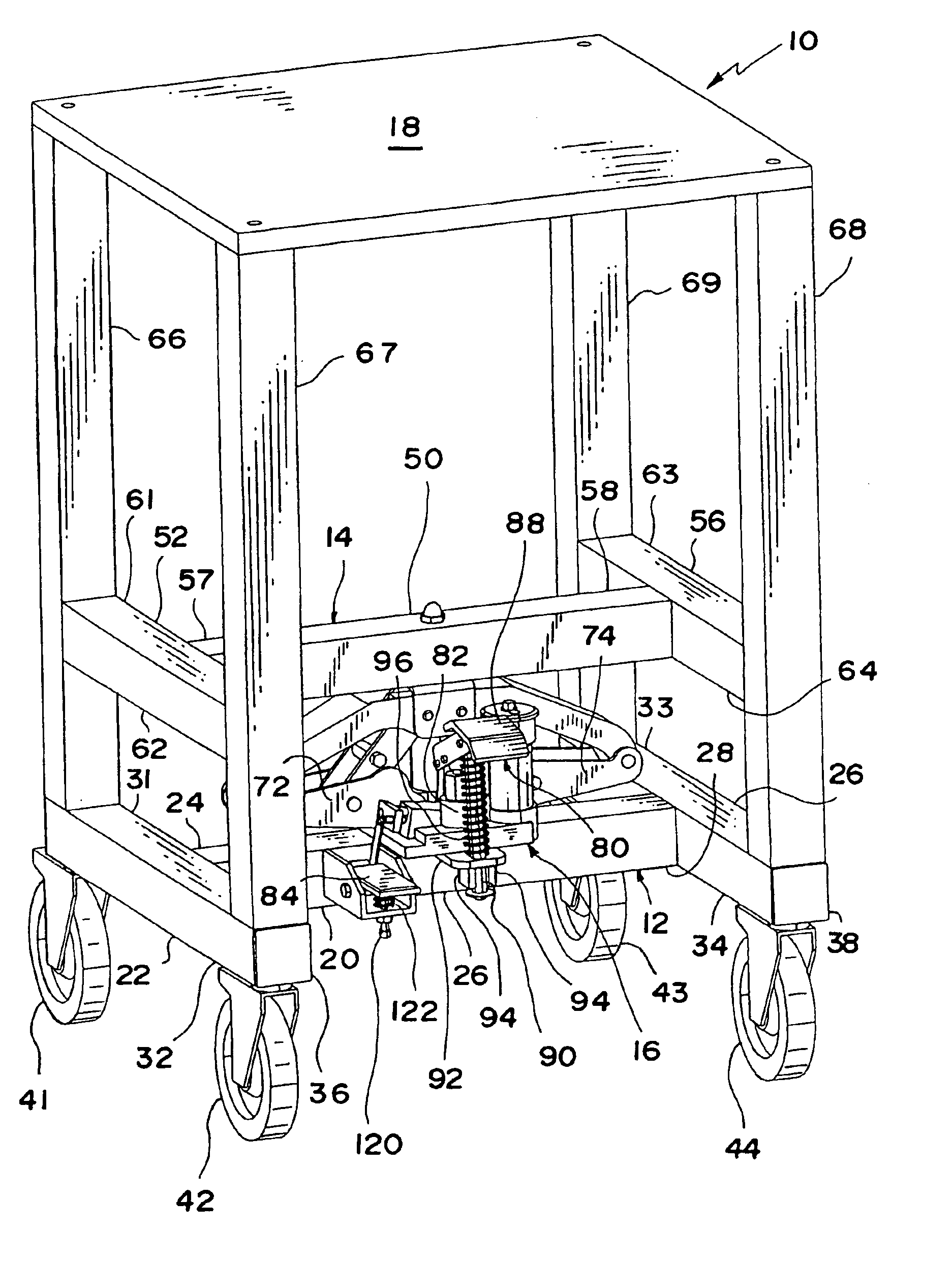
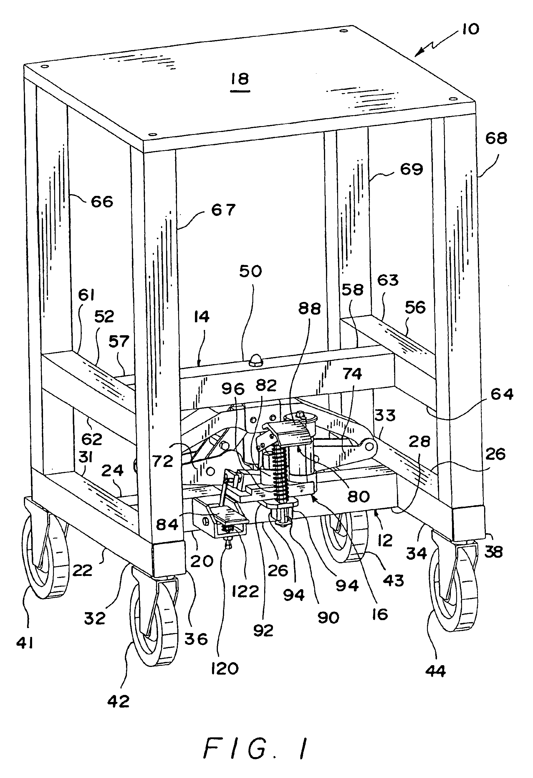
Although the present invention will be described hereinafter in the context of an adjustable height welding table for use in a machine shop, it will be appreciated that the invention is equally applicable to load bearing structures of many different types used in a variety of different applications. For example, the adjustable table can be used in office environments, restaurants or, for example, as a portable inspection station in a factory environment. Also please note that the terms vertically, horizontally, up, down and the like are used for convenience and simply refer to the table of the preferred embodiment of this invention in its natural upright position as shown in the drawings. These terms are therefore not to be considered limiting.

Referring to the drawings and initially to FIG. 1, an adjustable height table constructed in accordance with the invention is generally designated by the reference numeral 10 and includes an H-shaped base frame 12, an H-shaped slider frame ass...


PUM


Abstract

An adjustable height table includes a base frame, a slider frame assembly, a generally planar support surface and a lifting mechanism. The main portion of the base frame is formed by welding three tubular components to form an H-shape. Each of the end portions of the H-shape include a mounting to support a swiveling locking castor. Above each castor there extends from the H-shaped main portion, a vertically extending tubular post. The slider frame assembly preferably includes an H-shaped main portion formed of three tubular members. Four vertically extending hollow tubular column members are attached to the H-frame so that they may telescopingly engage the four vertically extending posts of the base frame. A generally planar support surface is attached to the top of the four vertically extending columns located on the slider frame. Located between the central tube of the H portion of the base frame and central tube of the slider frame assembly, there is located a lifting mechanism, preferably a hydraulic jack or a pair of electric motors. This jack can be actuated by a pedal mechanism to lift the slider frame assembly relative to the base frame. A second pedal is provided in the lifting mechanism to have the slider frame lower at a controlled rate of descent. Additionally an anti-sway bar is provided to prevent the lifting pump pedal from swaying side to side when in use.

Description

BACKGROUND OF THE INVENTION1. Field of the InventionThe present invention relates to adjustable height portable tables, and, more particularly, to a portable table which can be easily raised or lowered by using a jack.2. Description of Related ArtRecently there has become a need to have a portable and easily adjustable table which can vary its height. For the reasons discussed below, the table must be extremely stable and, in addition, be free from any type of clutter beneath its supporting surface. Such tables can find use in various environments, such as in offices, restaurants, factories and machine shops. For example, if the table were to be used as a welding fixture to support articles as they are welded together, it would be very important for the table to have all of the above-mentioned features. Therefore, it would be important that the table be portable so that it may be moved to whatever part of the shop that the welding is to be done. The table has to be extremely stable ...

Claims


Application Information

Patent Timeline
IPC IPC(8): A47B13/00A47B13/02A47B9/00A47B9/10A47B9/20
CPCA47B9/10A47B13/021A47B9/20
Inventor LANPHEAR, JOHN S.
Owner LANPHEAR JOHN S
Why Eureka
Try Eureka