Receive circuit for ultrasound imaging

a technology of receiving circuit and ultrasound, applied in the field of receiving circuit for ultrasound imaging, can solve the problems of inability to provide associated imaging in real time, poor contrast resolution of sparse array, and use of fully sampled two-dimensional arrays with expensive additional beamforming hardwar

Inactive Publication Date: 2005-04-05
SIEMENS MEDICAL SOLUTIONS USA INC
View PDF18 Cites 67 Cited by
  • Summary
  • Abstract
  • Description
  • Claims
  • Application Information

AI Technical Summary

Benefits of technology

The patent describes methods and systems for receiving different types of signals from different ultrasound transducers. The system has a connector and receiver circuit that can connect with different types of transducers. The receiver circuit processes the received information differently depending on the data format, such as the preamplifier impedance or gain and the low pass filter bandwidth. The technical effect of this patent is to enable the ultrasound system to receive and process different types of signals from different transducers with a single system, improving the flexibility and versatility of the ultrasound system.

Problems solved by technology

The technical problem addressed in this patent is the high cost and complexity of current receive circuits for ultrasound imaging, especially for real-time imaging of moving structures such as echocardiography. The current systems require high-voltage devices and expensive additional beamforming hardware, leading to increased space requirements and limited programmability. Additionally, the use of time division multiplexing to reduce the number of system channels and cables may result in the introduction of noise or errors in data. The invention provides a solution to simplify and reduce the cost of receive circuits for ultrasound imaging.

Method used


Image

  • Receive circuit for ultrasound imaging
  • Receive circuit for ultrasound imaging
  • Receive circuit for ultrasound imaging

Examples


Embodiment Construction

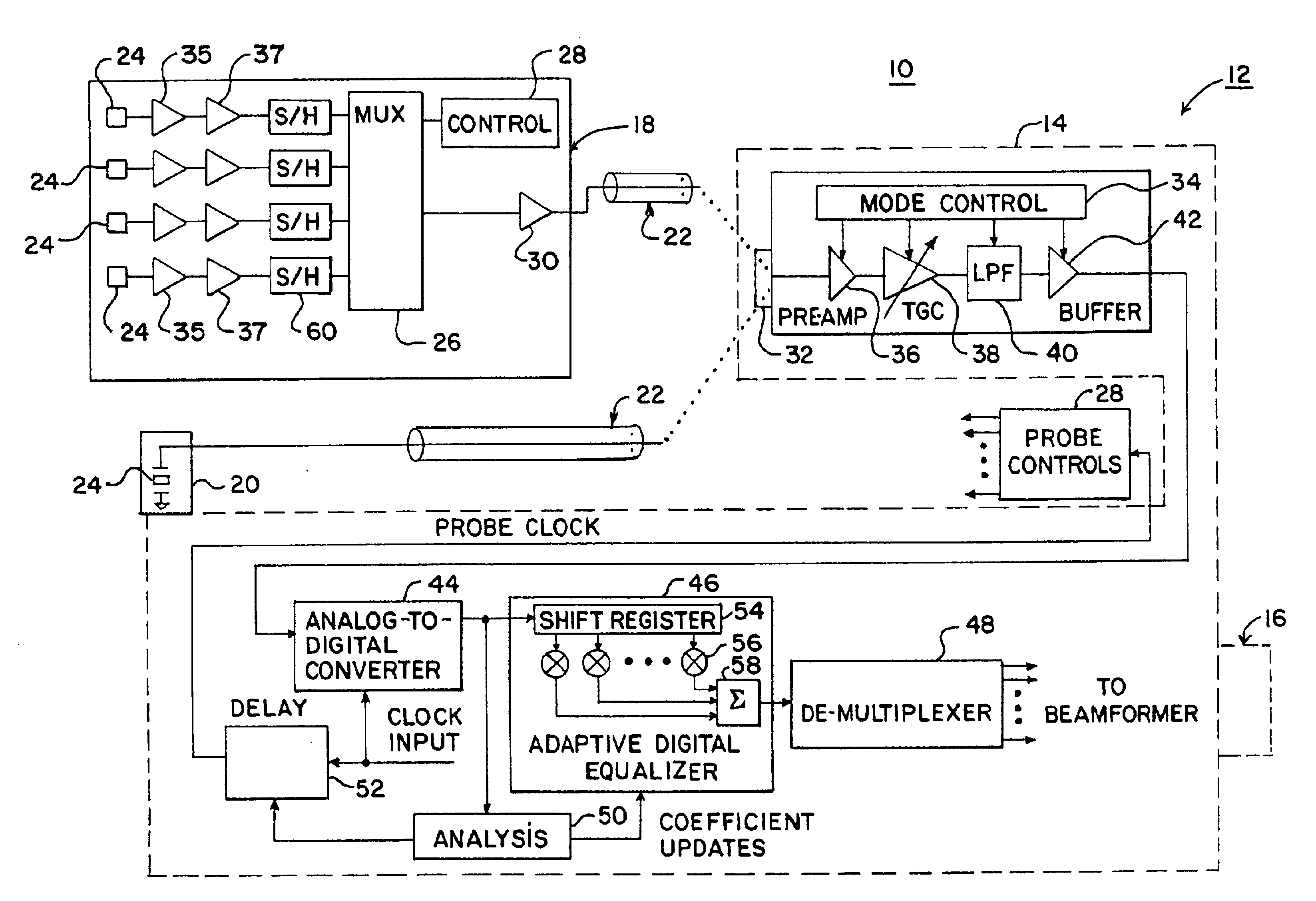
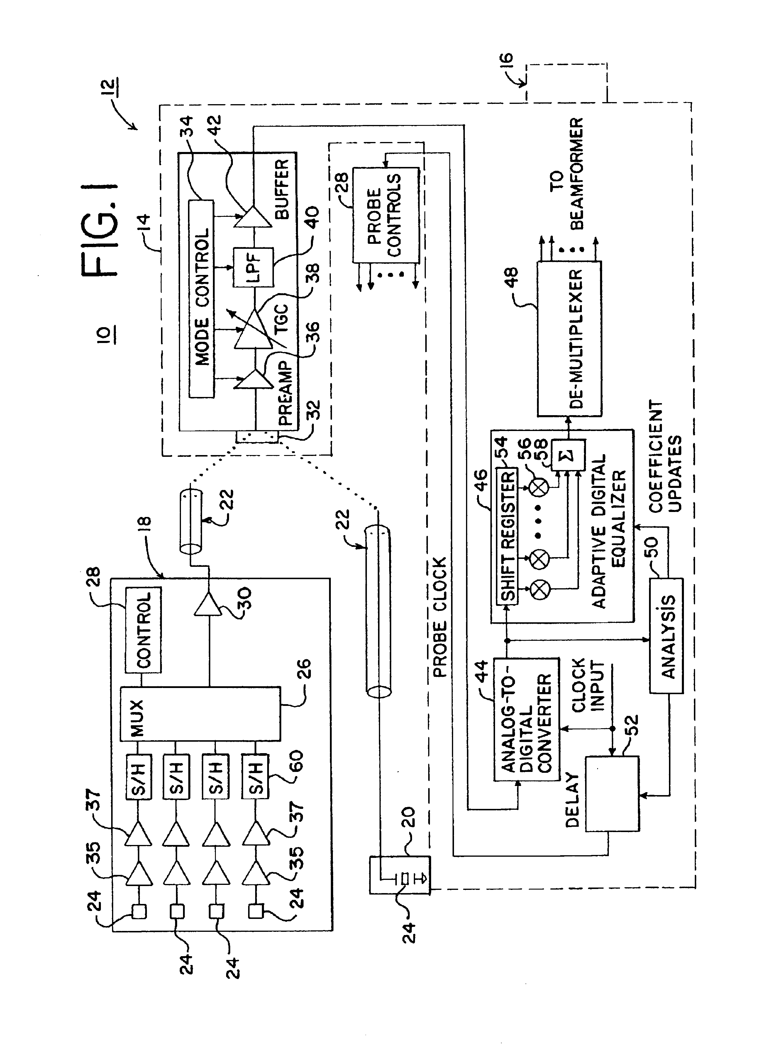
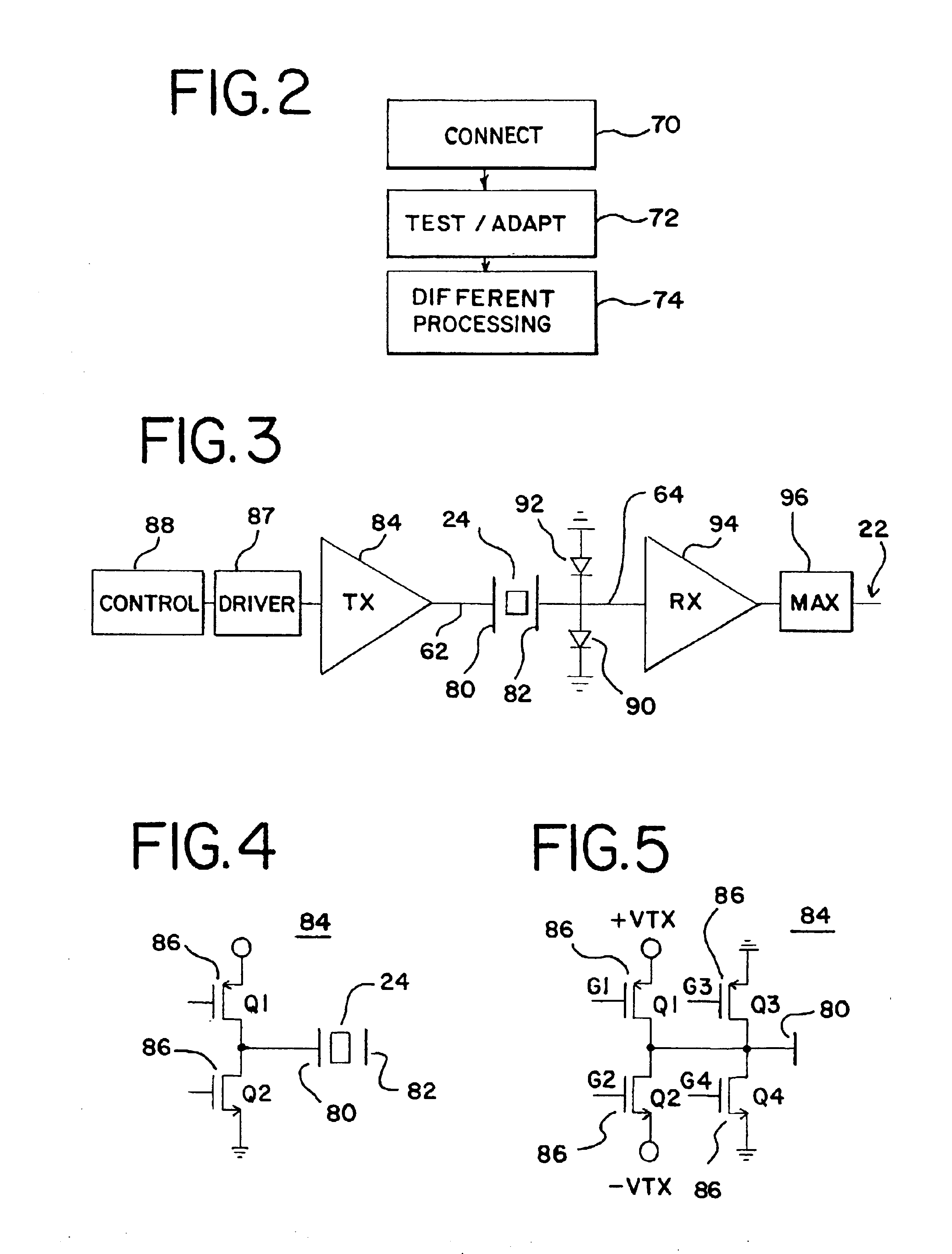
[0024]Faster or more complex two-dimensional and three-dimensional ultrasound imaging is provided by using multiplexing. A multiplexer is provided within a probe so that information from multiple transducer elements are multiplexed onto one signal channel for transmission to a base unit or ultrasound system for further processing. To avoid having different systems for different types of transducers, receive circuitry of an ultrasound system is operable in different modes based on the format of signals provided by the transducer. To further minimize the number of channels connecting a probe to an ultrasound system without adversely affecting the size of the probe, a transmit channel is separated from the receive channel by a transducer element. This separation isolates the transmit channel while minimizing integration of high voltage devices within the probe. To allow the element to isolate the transmit and receive channels, the transducer array is manufactured from separately diced ...


PUM


Abstract

Methods and systems for receiving different types of signal formats from different ultrasound transducers are provided. A base unit of an ultrasound system includes a connector and receiver circuit for connecting with one of multiple different types of transducers. For example, a conventional transducer providing analog information associated with a single element on one receive channel is connected with the connector and receiver circuit. Alternatively, a transducer outputting time division multiplex or other multiplex information representing multiple transducer elements is connected with the connector and receiver circuit. The receiver circuit processes the received information differently depending on the data format. For example, the preamplifier impedance or gain is different for single element signals versus time division multiplex signals. As another example, a low pass filter bandwidth is larger for time division multiplex signals than for signals representing a single element. Receive circuits with an analog-to-digital converter positioned prior to a digital demultiplexer are also included for use with multiplexed data formats. Time division multiplex or other multiplex signals from a transducer array are converted to a digital format prior to demultiplexing. Methods and systems for adapting multiplexing or processing of multiplexed signals are also provided. A test signal or ultrasound signals are transmitted from a transducer to the receiver circuit and analyzed. The multiplexer of the transducer is synchronized with an analog digital converter with selectable delays responsive to the analysis. Coefficients or other filter characteristics of a digital equalizer are selected as a function of the analysis.

Description


Claims


Application Information

Patent Timeline
Owner SIEMENS MEDICAL SOLUTIONS USA INC
Why Eureka
Try Eureka