Lancet for blood extraction

a technology for lancets and blood, which is applied in the direction of blood sampling devices, medical science, surgical saws, etc., can solve the problems that the lancets cannot be handled by actuating means, and the above-mentioned problems cannot be overcome, so as to prevent the pointed end section of the needle from being bent and prevent the lateral deflection of the head portion

Inactive Publication Date: 2005-04-05
WILDEN
View PDF7 Cites 94 Cited by
  • Summary
  • Abstract
  • Description
  • Claims
  • Application Information

AI Technical Summary

Benefits of technology

An object of the invention is to produce a lancet of a type referred to above in which the head portion may be separated from the base portion without a risk of unwanted or damaging effects being exerted on the lancet needle when preparing the lancet for a blood extraction operation. Another object of the invention is to produce a lancet of a type referred to above which may be used in conjunction with actuating means without a risk of causing problems when handling the lancet by such actuating means.
In accordance with the invention, this object is achieved by a lancet for the extraction of blood, including a base portion of plastics material, a lancet needle of a metallic material held in said base portion and having a pointed end section protruding from the base portion, a head portion of plastics material being integrally connected to the base portion by a preset breaking zone and adapted to be removed from the base portion thereby exposing the pointed end section of the lancet needle by exerting a rotational force to one of said base and head portions relative to the other, the lancet needle being embedded in the head portion prior to the removal thereof, and cam means on said base and head portions engaging with each other upon relative rotation between the head and the base portions for creating an axial movement of the head portion relative to the base portion. Thus in a lancet according to the present invention cam means are provided between the head portion and the base portion for producing an axial movement of the head portion relative to the base portion during a relative rotation between the head and base portions. Rather than for exposing the end section by pulling the head portion off the end section of the needle in a more or less uncontrolled manner by hands as this was hitherto usually done, this pulling now can occur in a controlled manner in that the cam means of a lancet according to the present invention ensures a precise axial movement of the head portion away from the base portion whilst substantially relieving the lancet needle of axial forces prior to and during the process of detaching the head portion from the base portion, since the head portion continues to be supported on the base portion during this operation. Consequently, there is no risk of withdrawing the lancet needle from the base portion, or, of inadvertently withdrawing the base portion from an actuating means. Moreover, the cam means simultaneously has the function of an anti-buckling means in that it reliably prevents the pointed end section of the needle from being bent by external lateral forces exerted on the head portion. While means for preventing lateral deflection of the head portion by more than a certain amount are known, by the prior anti-buckling measures the above-mentioned problems in regard to the handling of the lancet by actuating means could not be overcome. In a lancet according to the present invention a complete detachment of the head portion from the base portion requires but a short rotary movement of the head portion relative to the base portion without a need for further action by a user. The cam means can easily be formed together with other parts of the lancet by a plastics injection moulding process resulting in a preferred one-piece construction of the lancet.

Problems solved by technology

While means for preventing lateral deflection of the head portion by more than a certain amount are known, by the prior anti-buckling measures the above-mentioned problems in regard to the handling of the lancet by actuating means could not be overcome.

Method used


Image

  • Lancet for blood extraction
  • Lancet for blood extraction
  • Lancet for blood extraction

Examples


Embodiment Construction

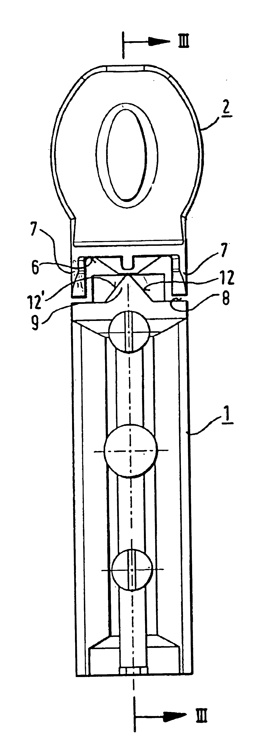
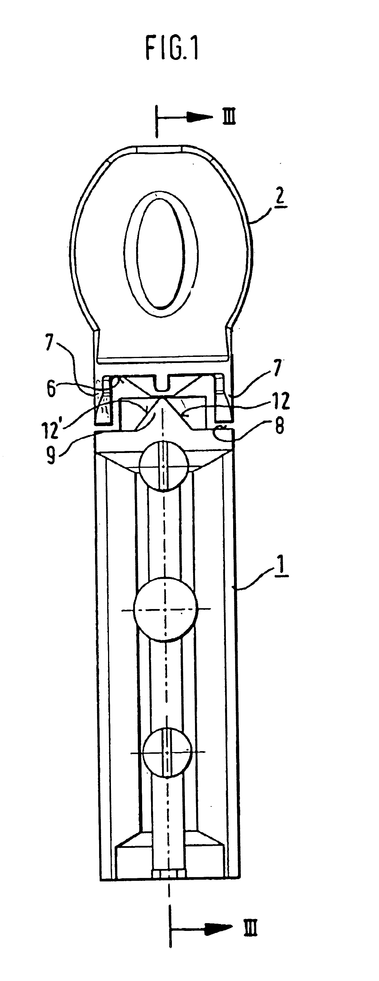
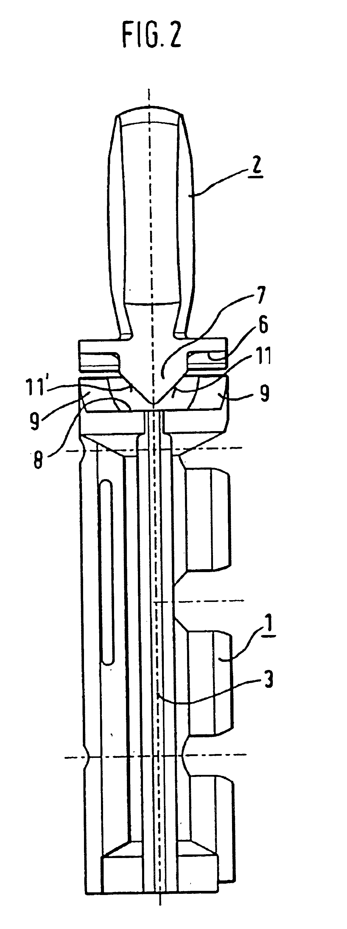
The lancet according to the present invention is shown in FIG. 1 and comprises a base portion 1 and a head portion 2. A lancet needle 3 is firmly held in the base portion 1. The base portion 1 and the head portion 2 are integrally connected with each other at a preset severing or breaking zone 4 which is shown in FIG. 3. The base portion 1 and head portion 2 of the lancet preferably is an injection moulded integral part of a suitable plastics material such as a polyolefine, e.g. polypropylene or polyethylene, but other plastics materials could be used if so desired. The preset breaking zone 4 is designed such that it can be caused to sever under the effect of an external force in order to separate the head portion 2 from the base portion 1. The preset breaking zone 4 may be in the form of a peripherally extending narrowing of the cross-section or it may be formed by a plurality of peripherally distributed, axially extending breakable webs. Other suitable constructions of the preset ...


PUM


Abstract

A lancet for the extraction of blood includes a base portion of plastics material, a lancet needle of a metallic material held in the base portion and having a pointed end section protruding from the base portion, a head portion of plastics material integrally connected to the base portion by a preset breaking zone, and cooperating cam means on the base and head portions. The head portion can be removed from the base portion thereby exposing the pointed end section of the lancet needle by exerting a rotational force to one of the base and head portions relative to the other. The lancet needle is embedded in the head portion prior to the removal thereof. The cam means comprises pairs of cooperating cam sections on the base and head portions engaging with each other upon relative rotation between these portions for creating an axial movement of the head portion relative to the base portion thereby causing a rupture of the preset breaking zone.

Description

FIELD OF THE INVENTIONThe invention relates to a lancet for the extraction of blood and especially to one comprising a lancet needle of a metallic material that is held in a base portion of plastics material and has a pointed end section protruding out from the base portion, in which the pointed end section of the needle is further embedded in a head portion of plastics material connected to the base portion by a preset breaking zone such that the head portion can be removed from the base portion prior to use thereby exposing the pointed end section of the needle if a rotational force is exerted on one of said base and head portions relative to the other portion.BACKGROUND OF THE INVENTIONLancets of this type are known from e.g. EP-A-589186 and similar designs have been in practical use for a long time. The head portion, in which the pointed end section of the lancet needle protruding from the base portion is embedded, ensures that the pointed end section of the needle is kept in a ...

Claims


Application Information

Patent Timeline
Patent Type & Authority Patents(United States)
IPC IPC(8): A61B5/15
CPCA61B5/1411A61B5/15142A61B5/150022A61B5/150412A61B5/15105A61B5/150549A61B5/150618A61B5/150717A61B5/150519
Inventor ARGAUER, HERBERT
Owner WILDEN
Why Eureka
Try Eureka