Eiga coil having annular turns

a technology of annular turns and coils, applied in the direction of coil arrangements, electric/magnetic/electromagnetic heating, additive manufacturing, etc., can solve the problems of short circuit interrupting the process flow, partially or completely blocking the nozzle,

Pending Publication Date: 2022-10-13
ALD VACUUM TECH GMBH
View PDF1 Cites 0 Cited by
  • Summary
  • Abstract
  • Description
  • Claims
  • Application Information

AI Technical Summary

Problems solved by technology

Instead, some droplets fall, for example, onto the edge or a frame of the cold inert gas nozzle, solidify there and may partially or completely clog the nozzle under certain circumstances.
Also, melted off droplets may hit the induction coil and cause a short circuit that interrupts the process flow.

Method used


Image

  • Eiga coil having annular turns
  • Eiga coil having annular turns
  • Eiga coil having annular turns

Examples


Embodiment Construction

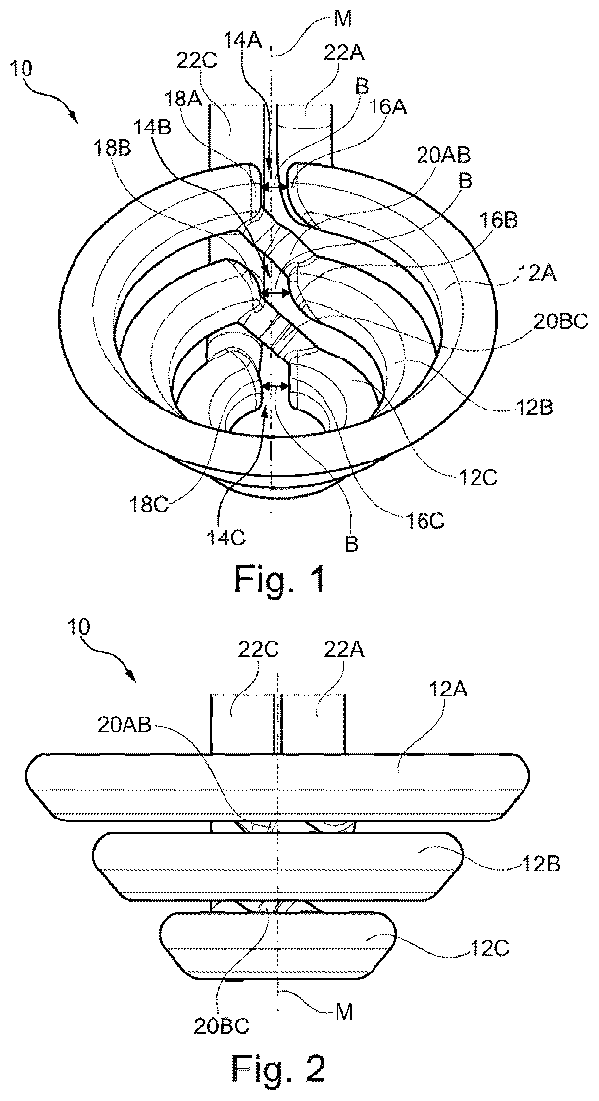
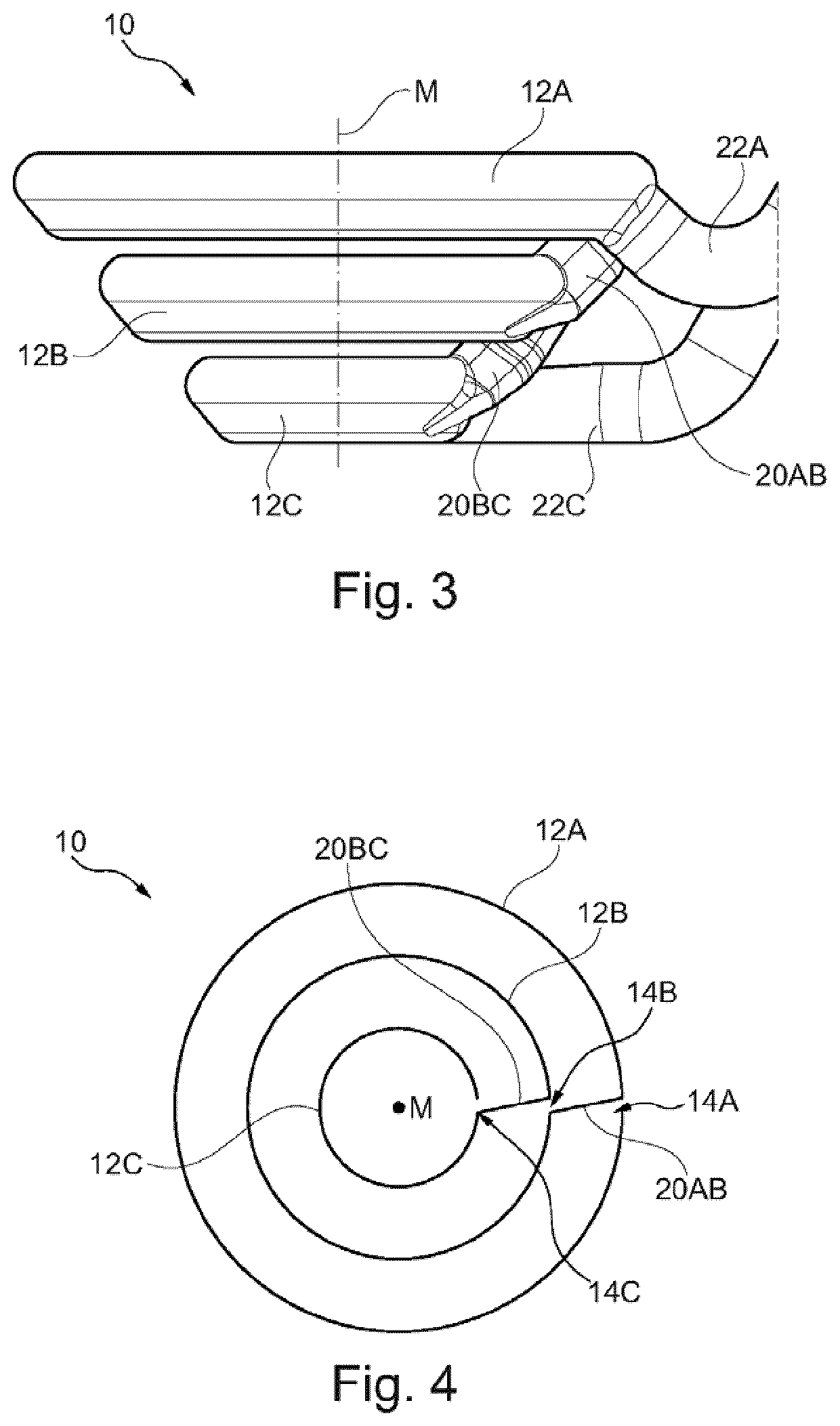
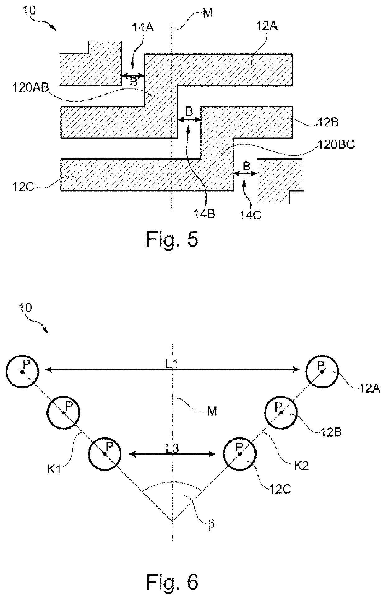
[0009]The EIGA coil according to the invention for partial melting on and melting off an electrode comprises a plurality of windings arranged coaxially to one another with respect to a center axis of the EIGA coil and axially spaced apart from one another. The center axis of the EIGA coil extends coaxial with a longitudinal axis of the electrode.

[0010]In the context of the present invention, the term EIGA coil refers to an induction coil for an EIGA system or for carrying out an EIGA method. The EIGA coil may comprise at least two windings, preferably at least three windings or even more than three windings.

[0011]According to the invention, each of the plurality of windings is in the form of a ring interrupted by a gap. The EIGA coil thus comprises a number of rings corresponding to the number of windings, wherein each of the rings is interrupted by a gap of small width and is thus not closed. More specifically, each of the rings is a ring segment comprising a first end and a second...


PUM

PropertyMeasurementUnit
inner diameteraaaaaaaaaa

Abstract

The invention relates to an EIGA coil (10) for partial melting an electrode (40). The EIGA coil (10) comprises a plurality of windings (12A, 12B, 12C) which are coaxially arranged with respect to a center axis (M) and axially spaced from each other, wherein each of the plurality of windings (12A, 12B, 12C) is formed in the shape of a ring interrupted by a gap (14A, 14B, 14C) and equidistant with respect to the center axis (M) and extending in a plane perpendicular to the center axis (M). Adjacent windings (12A, 12B; 12B, 12C) of the plurality of windings (12A, 12B, 12C) are respectively connected to each other via a connecting portion (20AB, 20BC; 120AB, 120BC).

Description

[0001]The present invention relates to an EIGA (Electrode Induction Melting (Inert) Gas Atomization) coil for partial melting an electrode for the production of high quality and pure metal powders. An EIGA coil refers to an induction coil for an EIGA system for performing an EIGA method. Furthermore, the present invention relates to an apparatus for performing an EIGA method and to an EIGA method for producing high-purity metal powder.BACKGROUND OF THE INVENTION[0002]The EIGA method for a ceramic-free production of high-purity metal or precious metal powders, such as powders of titanium, zirconium, niobium and tantalum alloys, is based on performing an electrode induction melting process. A vertically suspended rotating electrode is continuously supplied under vacuum or an inert gas atmosphere to a conical induction coil (EIGA coil) arranged below it and is partial melted or melted off contactless by means of the coil. The rotational movement of the electrode about its own longitudi...

Claims


Application Information

Patent Timeline
Patent Type & Authority Applications(United States)
IPC IPC(8): H05B6/18B33Y80/00B22F9/08H05B6/36
CPCH05B6/18B33Y80/00B22F9/082H05B6/367B22F2009/0848B22F2009/0836Y02P10/25B22F2998/00B22F2009/088C22C1/0425B22F2999/00B22F10/28B22F10/14B22F10/00
Inventor SPITANS, SERGEJSWINTON, MARKUSPFAHLS, FRANZFRANZ, HENRIKRADTKE, HANS-JÜRGEN
Owner ALD VACUUM TECH GMBH
Why Eureka
Try Eureka