Tube rack

a tube rack and tube technology, applied in the field of tube racks, can solve the problems of limiting the use of the tube rack, the cover may be opened inadvertently during shipment, and the rack cannot be tested, so as to achieve the effect of convenient manipulation

Inactive Publication Date: 2005-04-05
MATRIX TECH
View PDF39 Cites 124 Cited by
  • Summary
  • Abstract
  • Description
  • Claims
  • Application Information

AI Technical Summary

Benefits of technology

Advantageously, the rack of the present invention provides a convenient tube holder with a cover than can be easily manipulated by automated handling equipment.

Problems solved by technology

Conventional covered test tube racks suffer from various disadvantages that limit their usage under varying laboratory and shipping conditions.
For example, some racks lack a mechanism for securing the covers in their closed positions, thus presenting a danger that the cover may be inadvertently opened during shipment.

Method used


Image

  • Tube rack
  • Tube rack
  • Tube rack

Examples


Embodiment Construction

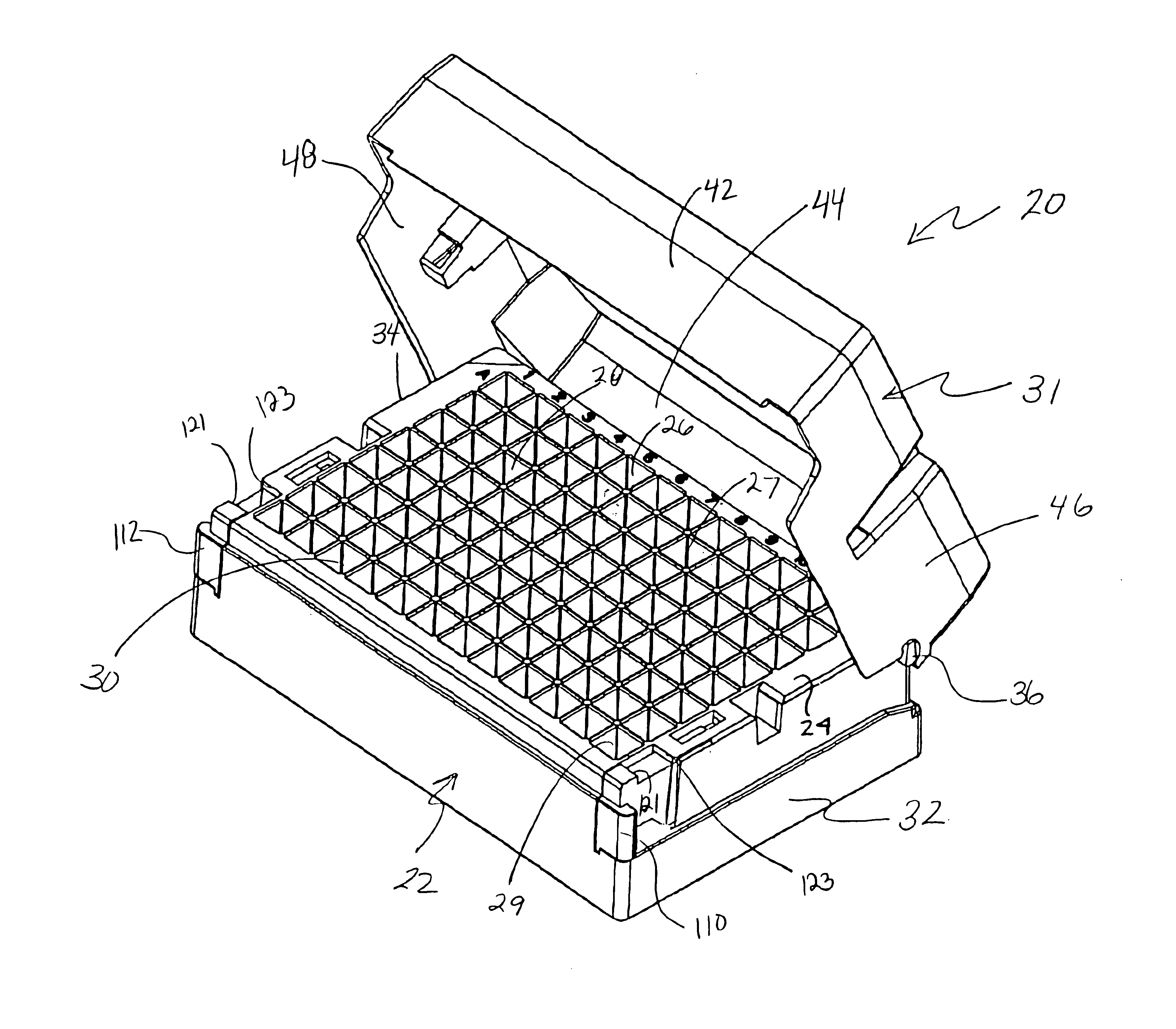
FIG. 1 is a perspective view of a tube rack 20 according to the present invention. The tube rack comprises a base 22 having an array of vertical openings 26-30. The rack 20 also includes a rotatable and removable cover 31 that cooperates with the base 22. As shown, the cover 31 is in a partial open position above the base 22.

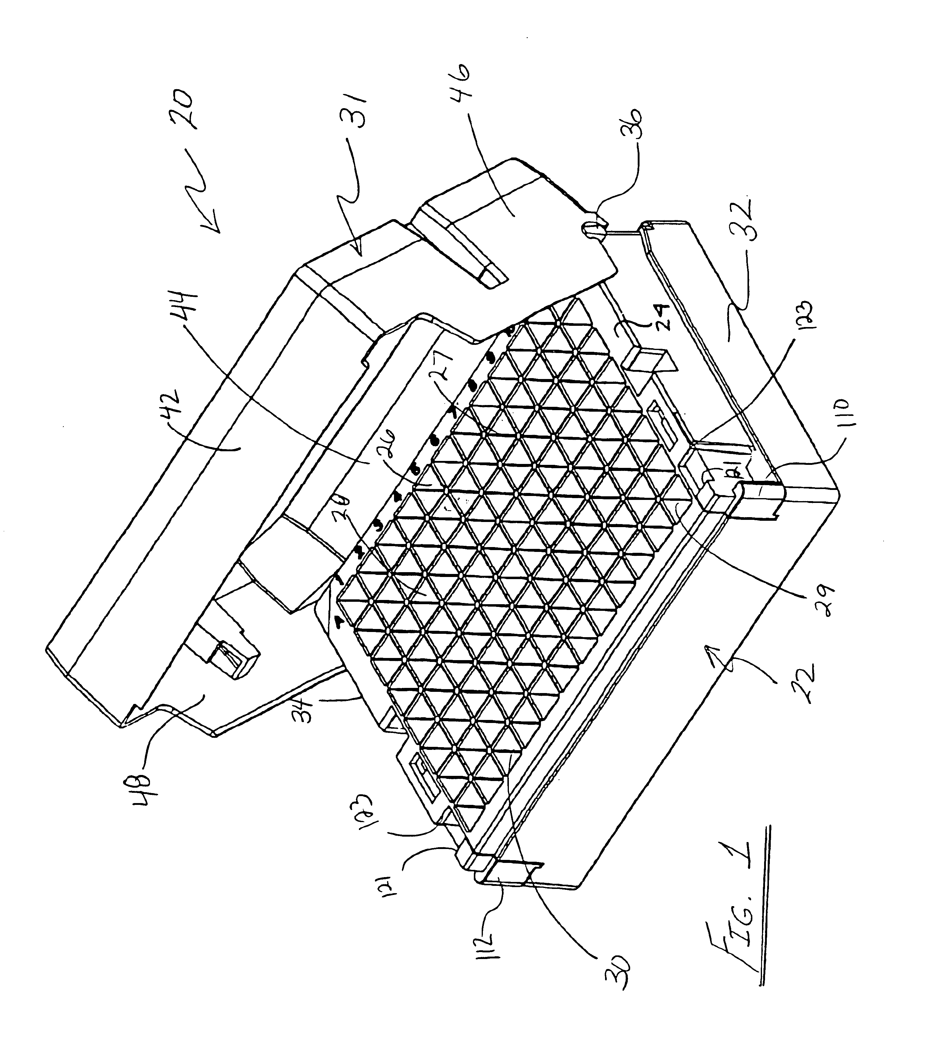
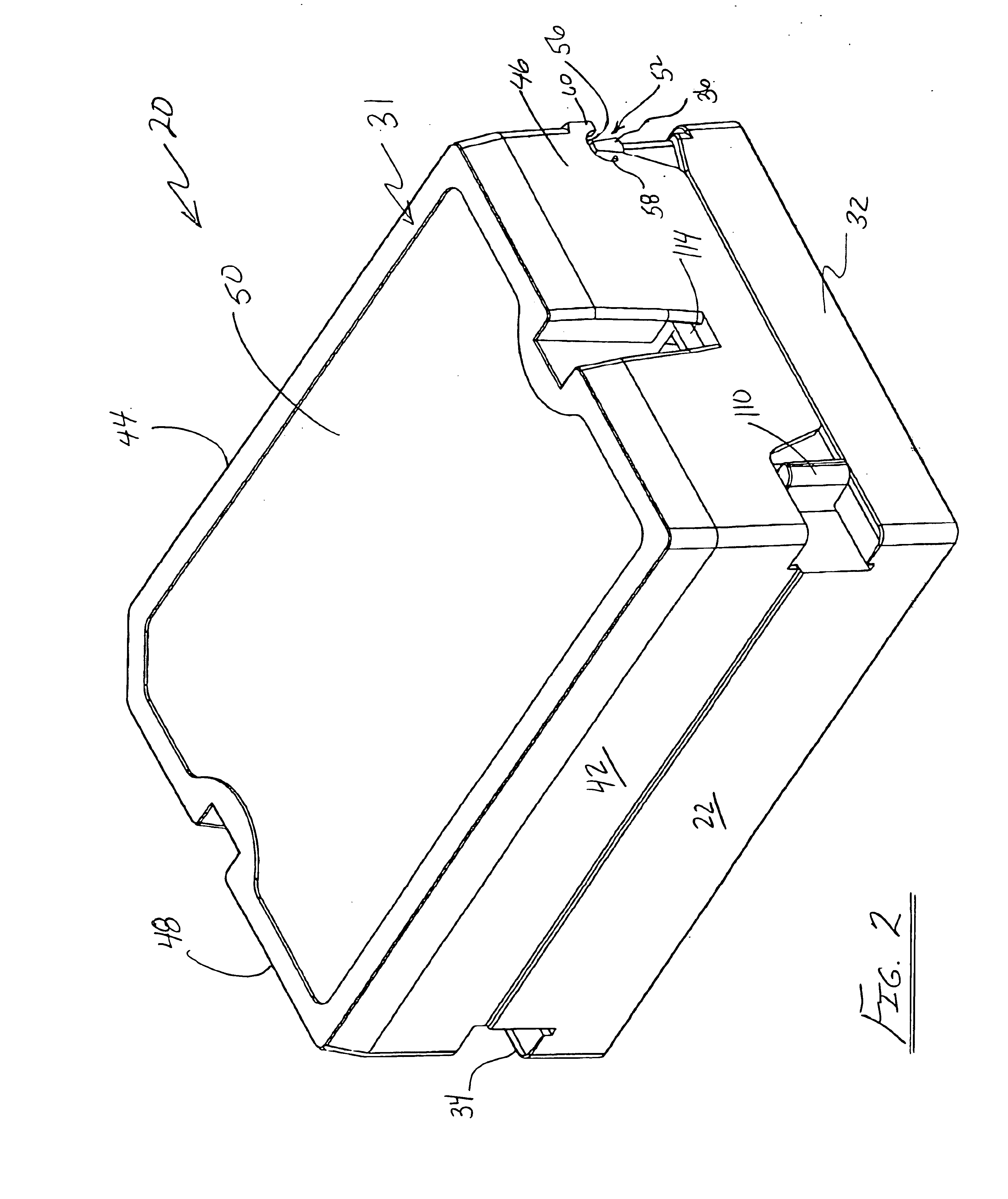
FIG. 2 is a perspective view of the tube rack 20 with the cover 31 in a closed position over the base 22.

FIG. 3 is a perspective view of the tube rack with the cover removed from the base.

Referring again to FIG. 1, the openings 26-30 are configured and dimensioned to receive a plurality of tubes (not shown), with upper ends of the tubes being accessible at the top surface 24. The base 22 also includes sidewalls 32, 34. Each of the sidewalls 32, 34 includes an associated co-axial trunnion 36, 38, respectively, extending from its associated sidewall. Trunnion 38 is not visible in the FIG. 3.

FIG. 4 is a top view of the base 22 illustrating the co-axial relationship...


PUM


Abstract

A tube rack comprises a base having an array of vertical openings extending therebetween, the openings being configured and dimensioned to receive a plurality of tubes, with the upper ends of the tubes being accessible at the top surface. The base includes base sidewalls that each include a co-axial trunnion extending from the associated sidewall. The tube rack also includes a rotatable and removable cover having a front wall, a back wall and first and second sidewalls, wherein the first and second side walls each include an associated notch open on a bottom surface thereof to allow the cover to be lowered onto the base, such that each of the notches rests on its associated trunnion and may be (i) vertically raised from its closed position on the trunnions and (ii) rotated about the trunnions from its closed position to allow access to the array of openings, wherein each of the notches includes a trunnion travel surface and a ledge surface and the ledge surface engages its associated trunnion to limit rotation of the cover beyond its full cover position. Each of the openings comprises a plurality of support pads positioned within the opening to vertically support the tube within its associated opening. Each of the pads includes a chamfered concave surface that supportably engages the tube, while providing flow paths through which air may pass through the openings adjacent to the tube.

Description

BACKGROUND OF THE INVENTIONThe present invention relates to test tube racks, and in particular to a tube rack having a multi-positional cover, wherein the rack is capable of receiving a variety of different tube styles and sizes.Conventional covered test tube racks suffer from various disadvantages that limit their usage under varying laboratory and shipping conditions. For example, some racks lack a mechanism for securing the covers in their closed positions, thus presenting a danger that the cover may be inadvertently opened during shipment. Other covers are permanently hinged to the rack bases, which precludes or at least significantly limits their usage with robotic test equipment.The present invention either obviates or at least significantly minimizes the above described problems by providing a test tube rack with a cover that may be locked in its closed position for shipment from one location to another, while it may be vertically removed from the rack base by robotic test eq...

Claims


Application Information

Patent Timeline
Patent Type & Authority Patents(United States)
IPC IPC(8): B01L9/00B01L3/00B01L9/06
CPCB01L9/06Y10S435/809
Inventor MATHUS, GREGORYSEGUIN, DANIEL J.TORTI, VICTOR A.
Owner MATRIX TECH
Why Eureka
Try Eureka