Apparatus for electromagnetic forming, joining and welding

Inactive Publication Date: 2005-04-05
FORD MOTOR CO
View PDF37 Cites 24 Cited by
  • Summary
  • Abstract
  • Description
  • Claims
  • Application Information

AI Technical Summary

Benefits of technology

Accordingly, it is an advantage of the present invention to provide a method of electromagnetic forming that can be opened and closed around tubular components thereby allowing EMF to take place regardless of surrounding componentry.
It is an advantage of the present invention to provide a method of cooling electromagnetic forming coils with a circulating coolant, thus minimizing overheating and long term coil degradation.
It is also an advantage of the present invention to direct the electromagnetic force to predetermined areas of the workpiece using spacers and slots machined therein.
The present invention provides these advantages with an apparatus for electromagnetic forming or joining of a workpiece, the apparatus comprising at least two multi-turn solenoid coils wound in a manner to cooperatively encircle the workpiece; an electrically insulative shell encasing each coil; an electromagnetic forming machine electrically connected to the coils and operative to generate

Problems solved by technology

The inductance generated with this individual segment coil design requires very high amounts of imputed energy to generate adequately secured joints.
The efficiencies of this coil design are insufficient for large-scale production and there is a need in the art for a more effective coil design.
A limitation of this design is the contact interface between the two coil halves when the electric current is moved

Method used


Image

  • Apparatus for electromagnetic forming, joining and welding
  • Apparatus for electromagnetic forming, joining and welding
  • Apparatus for electromagnetic forming, joining and welding

Examples


Embodiment Construction

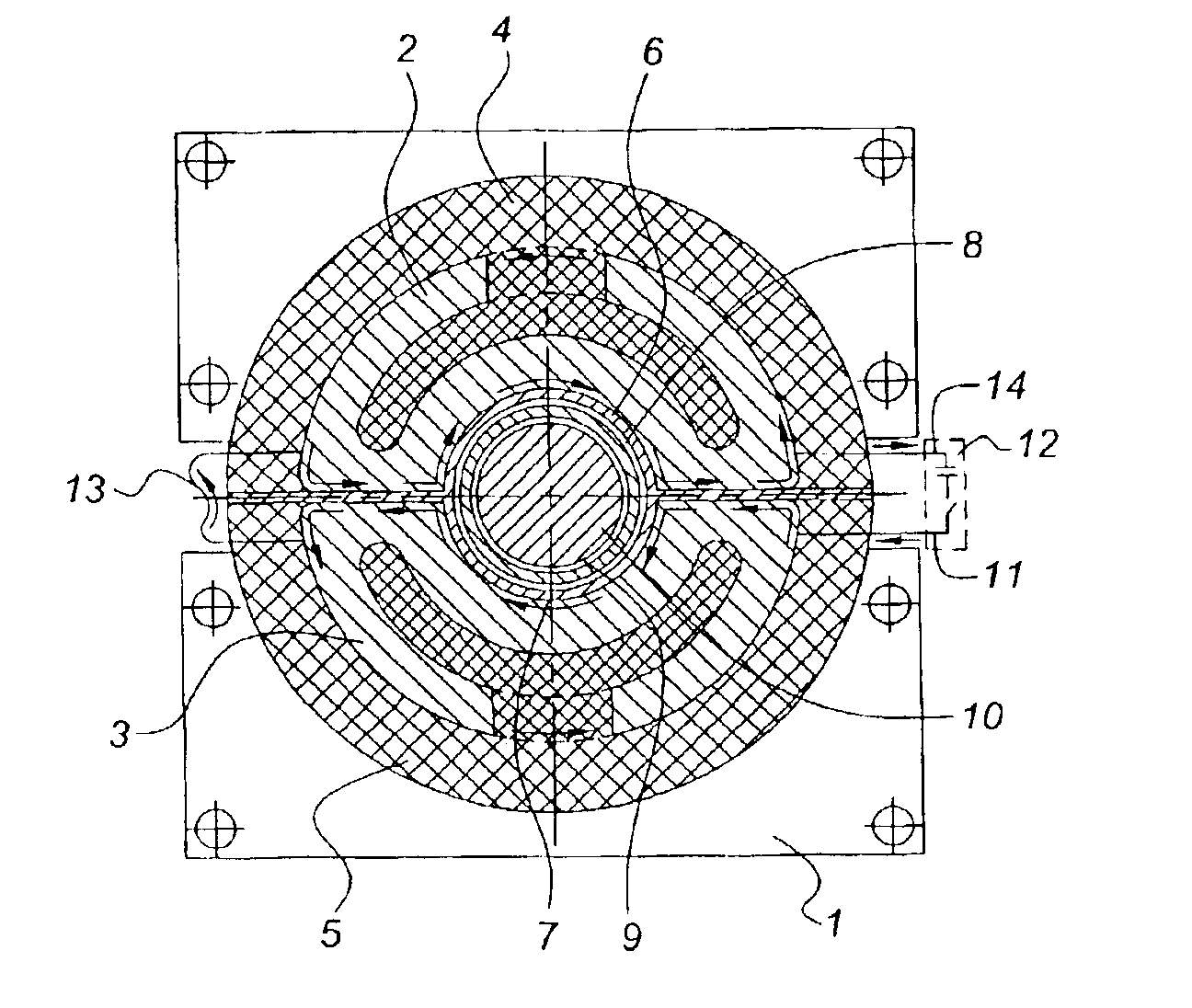
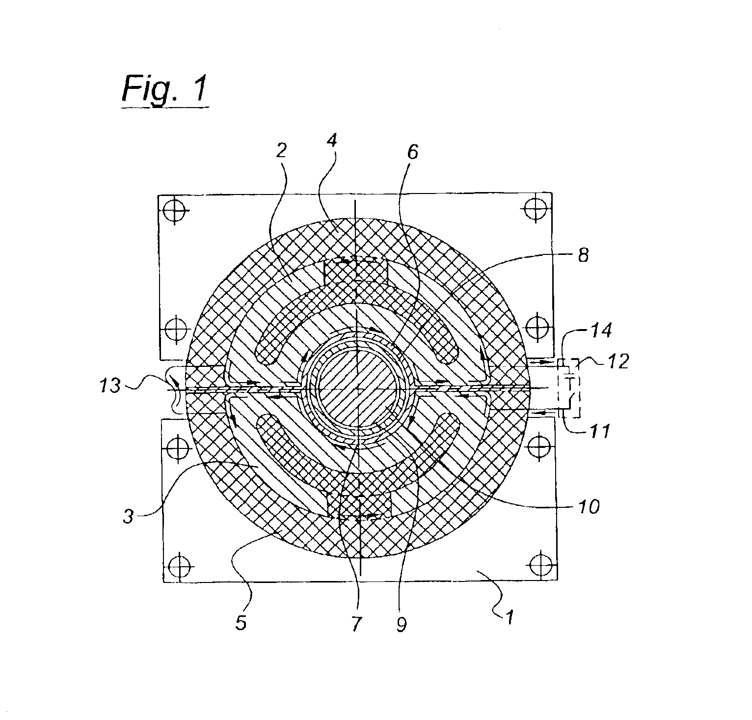
Referring now to the drawings, FIG. 1 illustrates a cross-sectional, side view of an apparatus for the electromagnetic forming or joining of a workpiece according to the present invention. Generally, electromagnetic forming machines force one workpiece against another workpiece resulting in the forming, joining or welding of the workpieces. A weld occurs when molecular interaction takes place between the two workpieces and they are merged together at the molecular level. Joining occurs where there is no molecular interaction between the two workpieces. “Forming” or “Electromagnetic Forming (EMF)” will be used to describe all such processes herein.

The electromagnetic forming apparatus shown in FIG. 1 includes a frame 1 housing the multi-turn solenoid coils 2 and 3 and their corresponding shells 4 and 5 made from an electrically insulative material. As illustrated, the coils 2 and 3 are positioned in such a way that concave work zones 6 and 7 are formed between the corresponding shell...


PUM

PropertyMeasurementUnit
Flow rateaaaaaaaaaa
Diameteraaaaaaaaaa
Currentaaaaaaaaaa

Abstract

There is disclosed herein an apparatus for electromagnetic forming, joining or welding a workpiece, the apparatus including at least two multi-turn solenoid coils wound in a manner that cooperatively encircles the workpiece to be formed. The apparatus also includes an electrically insulative shell encasing each coil and an electromagnetic current source electrically connected to the coils that generates an electromagnetic field. A hinge mechanism connects the insulative shells and a locking mechanism secures the shells and coils around the workpiece during electromagnetic field generation. A conductive rod joins the solenoid coils and permits series current flow between the coils. The apparatus further includes a shaper that encircles the workpiece and which restricts movement of the workpiece during electromagnetic forming. The shaper concentrates the generated electromagnetic field on the workpiece.

Description

BACKGROUND OF INVENTION1. Field of the InventionThe present invention relates generally to forming or joining of materials, and more particularly to an apparatus for the electromagnetic forming, joining or welding (EMF) of materials.2. Description of the Related ArtElectromagnetic forming has long been used as a method of manipulating tubular components. Electromagnetic forming forces one workpiece against another resulting in the welding or joining of the workpieces. A weld occurs when molecular interaction takes place between the two workpieces and they are merged together at the molecular level. Joining occurs where there is no molecular interaction between the two workpieces.U.S. Pat. Nos. 5,966,813; 6,104,012 and 5,981,921 disclose methods of joining tubular end fittings to drive shafts utilizing EMF. These patents incorporate a coil having individual segments connected in parallel similar to a coil design disclosed in U.S. Pat. No. 4,129,846. The inductance generated with this...

Claims


Application Information

Patent Timeline
IPC IPC(8): H05B6/14
CPCH05B6/14
Inventor GOLOVASHCHENKO, SERGEY FEDOROVICHDMITRIEV, VLADIMIR VLADIMIROVICHSHERMAN, ANDREW MICHAEL
Owner FORD MOTOR CO
Why Eureka
Try Eureka