Magnetic resonance imaging apparatus

Active Publication Date: 2020-03-05
HITACHI LTD
View PDF0 Cites 0 Cited by
  • Summary
  • Abstract
  • Description
  • Claims
  • Application Information

AI Technical Summary

Benefits of technology

[0012]According to the present invention, it is possible to obtain a magnetic resonance imaging apparatus capable of suitabl

Problems solved by technology

Particularly, when there is large low frequency vibration having a frequency of 100 Hz or less, it maybe unpleasant for some patients who are the subjects.
When the subject greatly vibrates, the acquired image maybe blurred and the image quality may be deteriorated in some cases.
On the other hand, the reaction force of the elect

Method used


Image

  • Magnetic resonance imaging apparatus
  • Magnetic resonance imaging apparatus
  • Magnetic resonance imaging apparatus

Examples


first embodiment

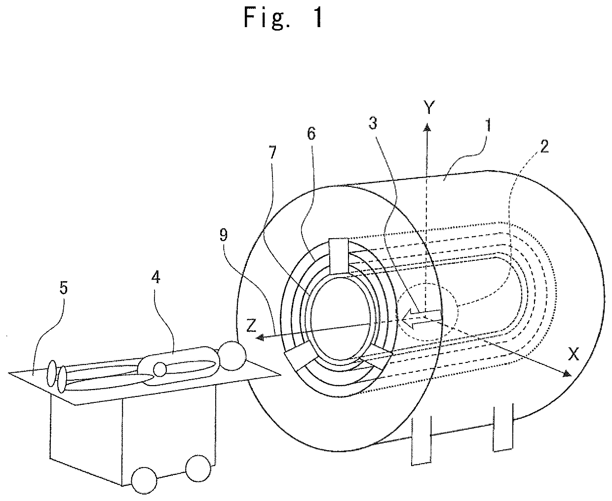
[0028]First, an overall configuration of a magnetic resonance imaging apparatus will be described with reference to FIG. 1. The magnetic resonance imaging apparatus (hereinafter referred to as “MRI apparatus”) includes a cylindrical magnetic pole 1 whose central axis is a Z axis 9 (CL, center line) , in which the magnetic pole 1 generates a static magnetic field in an imaging region 2 in the same direction as the Z axis 9 indicated by a void arrow 3 in FIG. 1. A subject 4 is carried to the imaging region 2 by a movable bed 5. The MRI apparatus processes a signal by a computer system (not illustrated) to obtain an image.

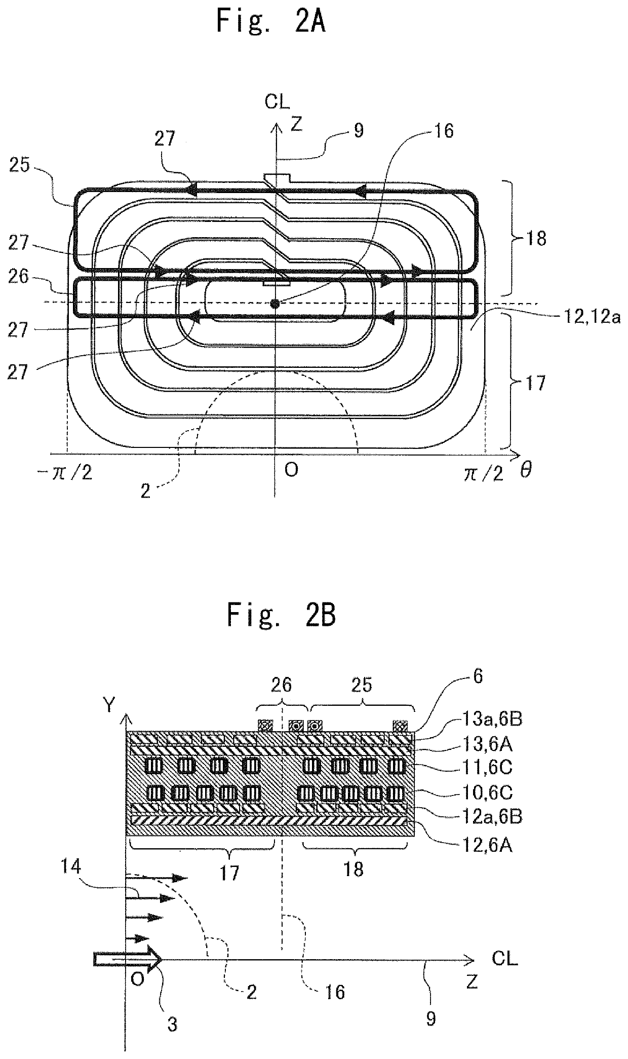
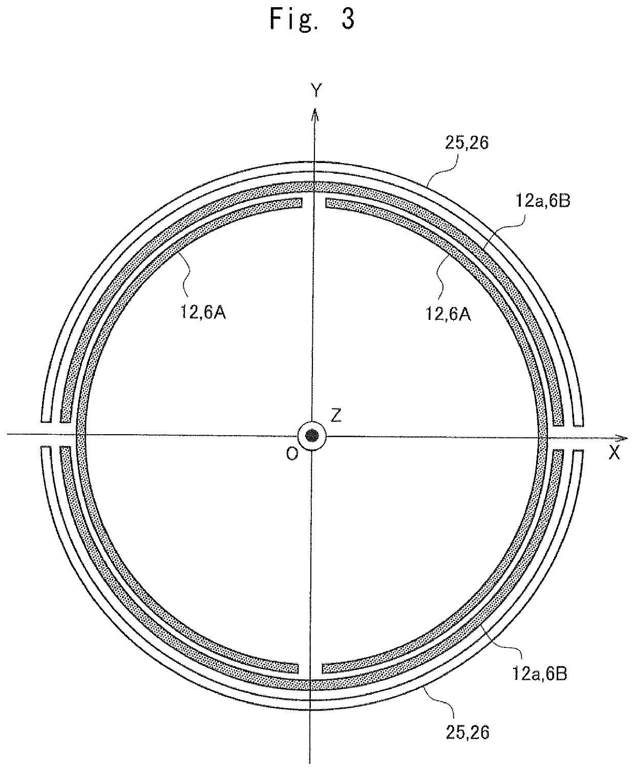
[0029]The MRI apparatus includes a cylindrical gradient magnetic field coil 6 disposed on a radially inner side of the magnetic pole 1 coaxially with the magnetic pole 1, and a cylindrical high frequency coil 7 arranged on a radially inner side of the gradient magnetic field coil 6 coaxially with the magnetic pole 1. The gradient magnetic field coil 6 generates a dyna...

second embodiment

[0053]Next, the MRI apparatus according to the second embodiment will be described with reference to FIG. 8. FIG. 8 is a top view illustrating a wiring structure of an additional coil with respect to the Y direction gradient magnetic field coil of a magnetic resonance imaging apparatus according to the second embodiment of the present invention.

[0054]In the present embodiment, the first additional coil 25 and the second additional coil 26 are formed of one electric current circuit. The first additional coil 25 and the second additional coil 26 share an electric current inflow / outflow path 33 connected to a power supply (not illustrated).

[0055]Each of the first additional coil 25 and the second additional coil 26 includes a conductor that intersects each other at an adjacent portion, and have a shape of approximately number ‘8’. As a result, the electric current circulating direction of the first additional coil 25 and the second additional coil 26 is reversed.

[0056]In the additional...

third embodiment

[0058]Next, the MRI apparatus according to the third embodiment will be described with reference to FIG. 9. FIG. 9 is a top view illustrating a wiring structure of an additional coil with respect to the Y direction gradient magnetic field coil of a magnetic resonance imaging apparatus according to the third embodiment of the present invention.

[0059]In the present embodiment, a third additional coil 34 is provided in addition to the first additional coil 25 and the second additional coil 26. The first additional coil 25, the second additional coil 26, and the third additional coil 34 are formed of one electric current circuit. The first additional coil 25, the second additional coil 26, and the third additional coil 34 share the electric current inflow / outflow path 33 connected to a power supply (not illustrated).

[0060]The first additional coil 25, the second additional coil 26, and the third additional coil 34 include conductors that intersect each other at an adjacent portion. As a...


PUM


Abstract

According to one embodiment, a magnetic resonance imaging apparatus includes: a cylindrical magnetic pole for generating a static magnetic field in an imaging region; a cylindrical gradient magnetic field coil arranged on a radially inner side of the magnetic pole, coaxially with the magnetic pole to generate a dynamic magnetic field having a linear magnetic field strength in the imaging region; a cylindrical high frequency coil arranged on a radially inner side of the gradient magnetic field coil, coaxially with the magnetic pole and the gradient magnetic field coil to generate a high frequency magnetic field in the imaging region; and a computer system for processing signals to obtain images. The magnetic resonance imaging apparatus further includes at least two loop-shaped additional coils arranged on the radially outer side of the gradient magnetic field coil and having different electric current circulating direction.

Description

BACKGROUND OF THE INVENTION1. Field of the Invention[0001]The present invention relates to a magnetic resonance imaging apparatus. More particularly, the present invention relates to a magnetic resonance imaging apparatus including a gradient magnetic field coil that generates a magnetic field having a gradient in strength at a spatial position in order to give position information to an imaging region.2. Description of the Related Art[0002]The magnetic resonance imaging apparatus mainly includes a magnet device, a gradient magnetic field coil, a high frequency coil, a receiving coil, and a computer system. The magnet device generates a uniform static magnetic field in the imaging region into which a subject is inserted. The gradient magnetic field coil generates the pulsed magnetic field (hereinafter referred to as “gradient magnetic field”) with strength gradient at a spatial position. The high frequency coil irradiates the subject with a high frequency pulse. The receiving coil r...

Claims


Application Information

Patent Timeline
IPC IPC(8): G01R33/385
CPCG01R33/3854G01R33/3858G01R33/4215
Inventor IMAMURA, YUKINOBUKUROME, AKIRAYATSUO, TAKESHI
Owner HITACHI LTD
Why Eureka
Try Eureka