Three-phase permanent magnet type motor

Active Publication Date: 2014-04-03
SANYO DENKI CO LTD
View PDF4 Cites 5 Cited by
  • Summary
  • Abstract
  • Description
  • Claims
  • Application Information

AI Technical Summary

Benefits of technology

The invention relates to a circuit configuration for reducing electromagnetic force and torque ripple in a rotor. It achieves this by connecting adjacent in-phase windings in parallel and in series with like-pole windings of a symmetrical in-phase second winding group facing at a 6-slot pitch angle. Additionally, the invention arranges an in-phase transition wiring pattern on the same layer of a multilayer wiring board in a line symmetrical manner, reducing the number of layers and manufacturing cost of the board.

Problems solved by technology

When using the multilayer printed wiring boards of the five layers or more, there has been a problem in that a manufacturing cost increases.
Furthermore, the conventional two parallel connection structure has problems in that an electromagnetic force acting as a factor causing a rotor eccentricity due to imbalance of a winding impedance increases, and a torque ripple acting as a factor causing the speed fluctuation increases.
However, according to the technique of Japanese Patent Application Laid-Open Publication No. 2010-193675, the workability is likely to worsen, and the manufacturing cost of the multilayer wiring board increases.

Method used


Image

  • Three-phase permanent magnet type motor
  • Three-phase permanent magnet type motor
  • Three-phase permanent magnet type motor

Examples


first embodiment

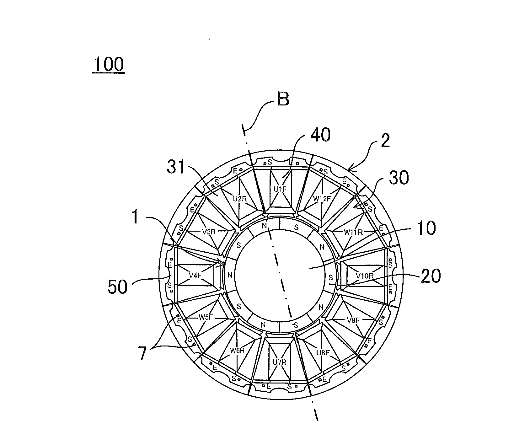
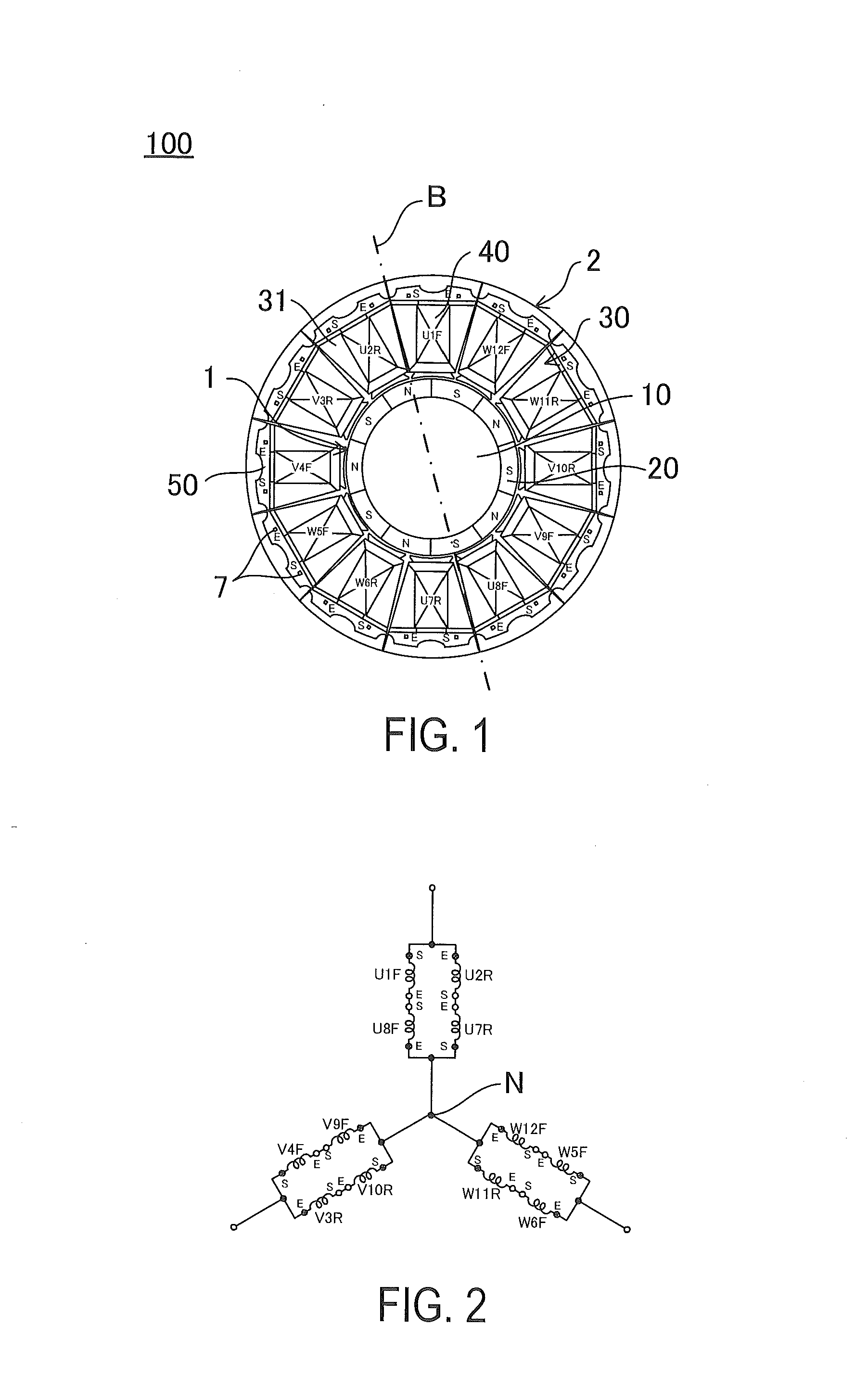
[0036]First, a configuration of the three-phase permanent magnet type motor of the first embodiment will be described with reference to FIG. 1. FIG. 1 is a schematic cross-sectional view of a three-phase permanent magnet type motor according to the first embodiment.

[0037]As illustrated in FIG. 1, for example, a three-phase permanent magnet type motor 100 of the first embodiment is configured as an SPM motor (Surface Permanent Magnet Motor) with 10 poles and 12 slots.

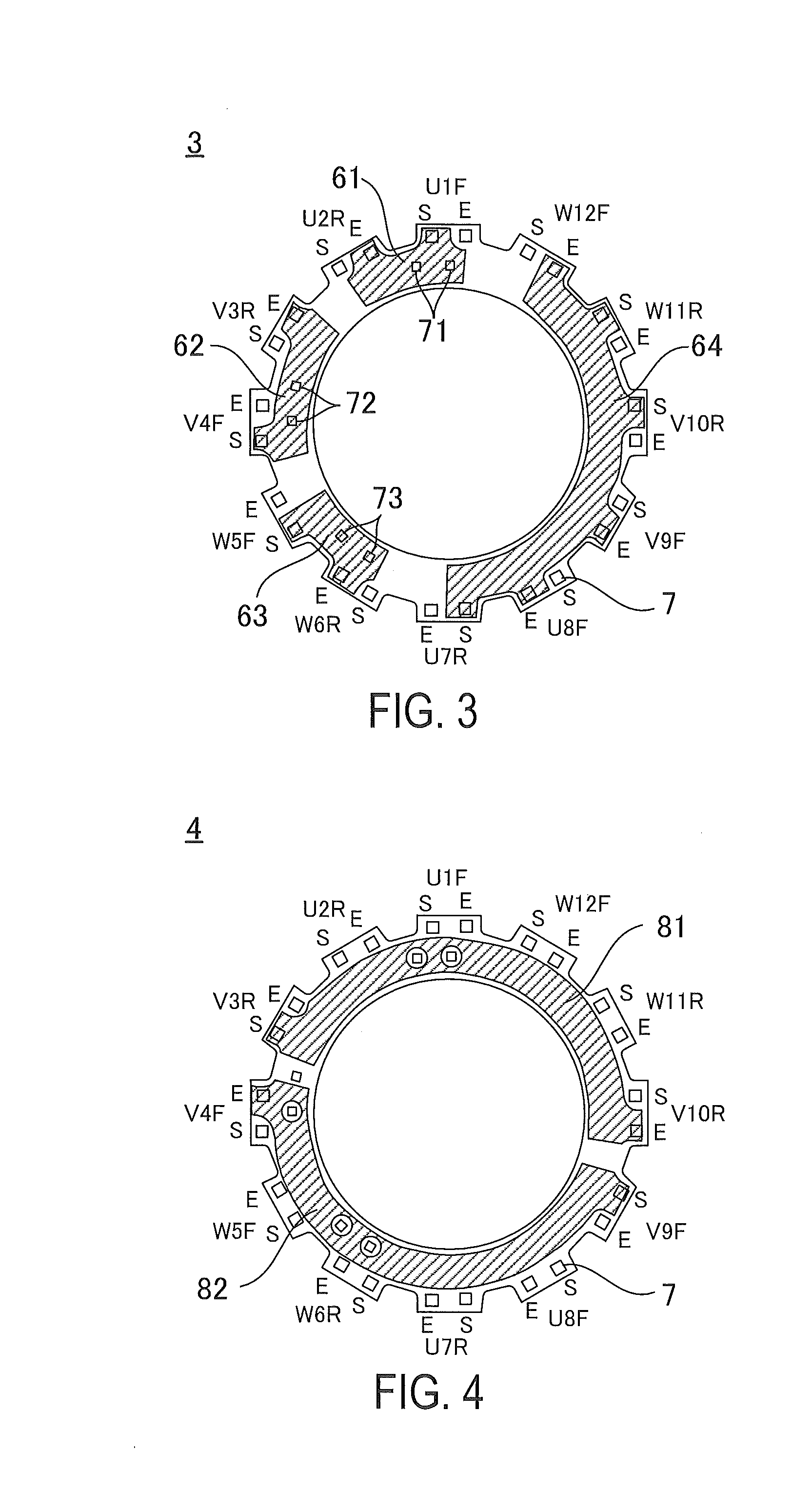
[0038]The three-phase permanent magnet type motor 100 of the present embodiment includes a rotor 1, a stator 2, and multilayer wiring boards 3 to 6.

[0039]The rotor 1 has a rotor core 10 and a permanent magnet 20.

[0040]The rotor core 10 is a cylindrical metallic member. As structural materials of the rotor core 10, for example, soft magnetic materials such as silicon steel plate are used, but the materials are not limited to the exemplary material.

[0041]The rotor 1 of the SPM motor is configured so that a ring-shaped perm...

second embodiment

[0083]Next, a configuration of a three-phase permanent magnet type motor of a second embodiment will be described with reference to FIG. 7. FIG. 7 is a schematic cross-sectional view of the three-phase permanent magnet type motor according to the second embodiment. In addition, the same structural members as those of the first embodiment will be described while being denoted by the same reference numerals.

[0084]A three-phase permanent magnet type motor 200 according to the second embodiment is different from that of the first embodiment in the arrangement of the division core 31, the arrangement of the windings of three-phase Y connection, and the structures of the multilayer wiring boards 203 to 206.

[0085]In FIG. 7, reference numerals added on the winding 40 will be described. A positional relation between a circuit connection diagram described below and the multilayer wiring board becomes clear, by the reference numerals of each winding 40. First, the distinctions of the three pha...

third embodiment

[0112]Next, a configuration of a three-phase permanent magnet type motor according to a third embodiment will be described with reference to FIG. 13. FIG. 13 is a schematic cross-sectional view of the rotor used in the three-phase permanent magnet type motor according to the third embodiment. In addition, the same structural members as those of the first embodiment will be described while being denoted by the same reference numerals.

[0113]A three-phase permanent magnet type motor 300 according to the third embodiment is different from that of the first embodiment in a structure of a rotor 301.

[0114]For example, a rotor 301 illustrated in FIG. 13 is configured as a consequent pole type IPM motor (Interior Permanent Magnet Motor) with 10 poles.

[0115]The rotor 301 is provided around the rotary shaft 8, and has a rotor core (an iron core) 310, and a permanent magnet 320. The rotary shaft 8 serves as a center of rotation of the rotor 301.

[0116]The rotor core 310 is a metallic member havi...


PUM


Abstract

A three-phase permanent magnet type motor has a stator in which a plurality of windings wound in a same direction are disposed, and the number of slots is 12n; a rotor in which the number of poles of the permanent magnet is 10n or 14n; and multilayer wiring boards for performing the connection so as to be 2m parallel. The three-phase permanent magnet type motor has a circuit configuration in which, among U-phase, V-phase, and W-phase, adjacent in-phase windings are connected in parallel and are connected in series with a like-pole winding of a symmetrical in-phase second winding group facing at 6-slot pitch angle, when a center of a first winding group of the adjacent in-phase windings is set as a reference axis, and in-phase transition wiring patterns are disposed on the same layer of the multilayer wiring boards in a line symmetrical manner.

Description

BACKGROUND[0001]1. Technical Field[0002]The invention relates to a three-phase permanent magnet type motor including a multilayer wiring board that connects windings of a motor in which the number of slots is equal to an integer multiple of 12, and the number of poles is equal to an integer multiple of 10 or an integer multiple of 14.[0003]2. Description of Related Arts[0004]In the prior art, a two parallel connection of a three-phase permanent magnet type motor with 10 or 14 poles and 12 slots has been performed using multilayer printed wiring boards of five layers or more. When using the multilayer printed wiring boards of the five layers or more, there has been a problem in that a manufacturing cost increases.[0005]Furthermore, the conventional two parallel connection structure has problems in that an electromagnetic force acting as a factor causing a rotor eccentricity due to imbalance of a winding impedance increases, and a torque ripple acting as a factor causing the speed flu...

Claims


Application Information

Patent Timeline
IPC IPC(8): H02K3/00
CPCH02K3/00H02K3/28H02K3/522H02K2203/03H02K3/34H02K21/14
Inventor MIYASHITA, TOSHIHITOYAMAGUCHI, MASAHIRO
Owner SANYO DENKI CO LTD
Why Eureka
Try Eureka