Normally closed solenoid valve

a solenoid valve and valve body technology, applied in the direction of valve details, valve arrangement, valve operating means/release devices, etc., can solve the problems of fine pressure control and flow control cannot be performed, and achieve the effect of prolonging the life of the normally closed solenoid valve, preventing erosion, and suppressing damage to the seal portion

Active Publication Date: 2015-02-12
TOYOTA JIDOSHA KK
View PDF18 Cites 3 Cited by
  • Summary
  • Abstract
  • Description
  • Claims
  • Application Information

AI Technical Summary

Benefits of technology

[0017]Further, in the normally closed solenoid valve according to one embodiment of the present invention, the load adjusting mechanism is capable of adjusting the load of the first spring, and the stroke adjusting mechanism is capable of adjusting the unseating stroke of the valve element from the valve seat (which may hereinafter be referred to simply as “stroke”). Thus, in the normally closed solenoid valve according to one embodiment of the present invention, not only in the fluid control for the flow in the self-opening direction, but also in the fluid control for the flow in the self-closing direction, the above-mentioned force of the fluid, loads of both the springs, electromagnetic force, and the like are balanced, with the result that fine pressure control and flow control can be performed through fine adjustment using the electromagnetic force.
[0018]When carrying out the invention described above, the load of the second spring may be set to zero before the unseating stroke of the valve element from the valve seat becomes maximum (before the maximum stroke is obtained). In this case, the load of the first spring at the time when the unseating stroke of the valve element from the valve seat becomes the maximum (at the time of maximum stroke) can be set lower than, for example, in a case where the load of the second spring is set to zero at the time of maximum stroke. Thus, the electromagnetic force necessary to obtain the maximum stroke of the valve element and the movable core (necessary current) can be reduced, with the result that the normally closed solenoid valve can be constructed into a power-saving type.
[0019]Further, when carrying out the invention described above, the one end portion side of the valve orifice (valve seat side) may communicate to the inflow port, and another end portion side of the valve orifice may communicate to the outflow port. In this case, cavitation and erosion may occur on a downstream side with respect to a seal portion (portion at which the valve element is seated on the valve seat), and hence the erosion can be prevented from occurring in the vicinity of the seal portion, with the result that the normally closed solenoid valve can be constructed into an anti-erosion type (damage to the seal portion can be suppressed and the life of the normally closed solenoid valve can therefore be prolonged).

Problems solved by technology

In fluid control for a flow in a self-closing direction (that is, a flow of the fluid in a case where the force of the fluid flowing from the inflow port to the outflow port of the housing is to be received by the valve element in a seating direction), however, the above-mentioned force of the fluid, loads of both the springs, electromagnetic force, and the like are not balanced (the above-mentioned force of the fluid and load of the second spring are applied to the valve element toward the valve seat, and hence the valve element is not unseated from the valve seat even when the electromagnetic force is adjusted in any way), with the result that the fine pressure control and flow control cannot be performed.

Method used


Image

  • Normally closed solenoid valve
  • Normally closed solenoid valve
  • Normally closed solenoid valve

Examples


Embodiment Construction

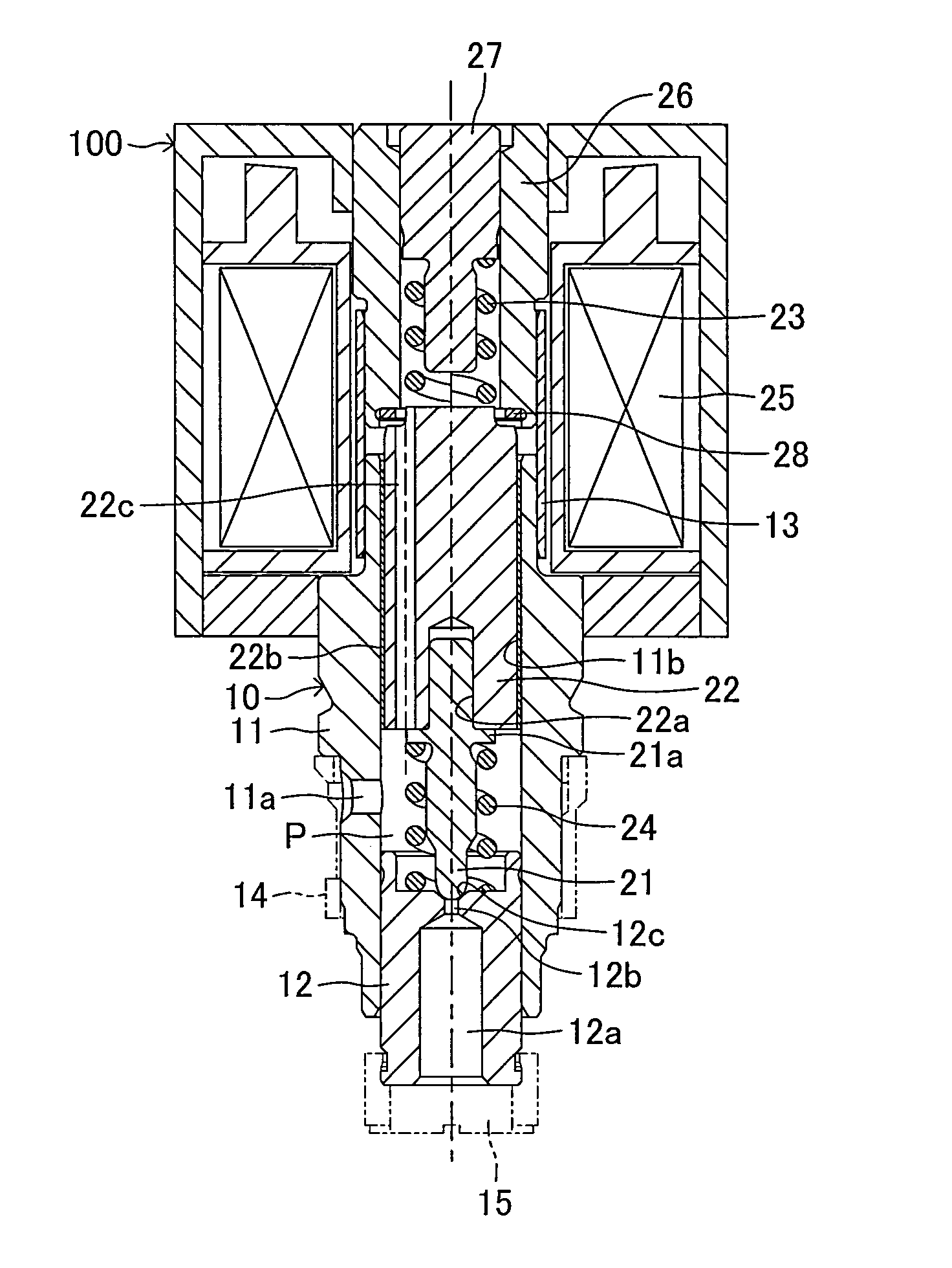
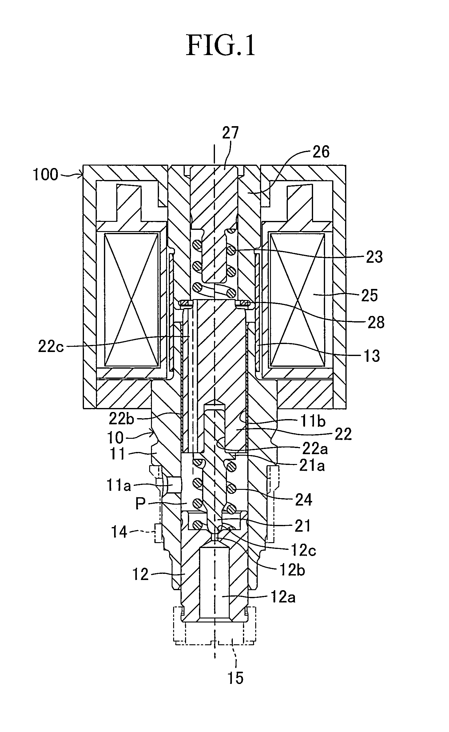
[0027]Now, embodiments of the present invention are described with reference to the drawings. FIG. 1 illustrates a normally closed solenoid valve according to an embodiment of the present invention. A normally closed solenoid valve 100 of this embodiment is assembled to, for example, a hydraulic pressure control device of a hydraulic brake apparatus for a vehicle, and is used for controlling a hydraulic pressure of a brake fluid. The normally closed solenoid valve 100 includes a valve element 21, a movable core 22, a first spring 23, a second spring 24, a coil 25, a stator core 26, and other components, which are assembled to a housing 10.

[0028]The housing 10 includes a cylindrical guide member 11, a cylindrical seat member 12 assembled to an inner periphery of a lower end portion of the guide member 11 in FIG. 1 so that the position of the seat member 12 is adjustable in a vertical direction, and a sleeve 13 assembled to an outer periphery of an upper end portion of the guide membe...


PUM


Abstract

A normally closed solenoid valve (100) includes a housing (10), and a valve element (21), a movable core (22), a first spring (23), a second spring (24), a coil (25), a stator core (26), and other components, which are assembled to the housing (10). The valve element (21) is arranged so as to be seatable on and unseatable from a valve seat (12c). The movable core (22) is assembled to a cylinder section (11b) of the housing (10) so as to be movable integrally with the valve element (21) in an axial direction of the movable core (22). The first spring (23) is configured to bias the valve element (21) and the movable core (22) toward the valve seat (12c). The coil (25) and the stator core (26) are configured to generate an electromagnetic force resistive to a load of the first spring (23) for the movable core (22) through energization of the coil (25). The second spring (24) is configured to apply a load smaller than and resistive to the load of the first spring (23) to the valve element (21) and the movable core (22). The normally closed solenoid valve (100) further includes a load adjusting mechanism capable of adjusting the load of the first spring (23), and a stroke adjusting mechanism capable of adjusting an unseating stroke of the valve element (21) from the valve seat (12c).

Description

TECHNICAL FIELD [0001]The present invention relates to a normally closed solenoid valve, and more particularly, to a normally closed solenoid valve capable of performing fine pressure control and flow control.BACKGROUND ART[0002]The normally closed solenoid valve of this type is disclosed in, for example, Patent Literature 1. The normally closed solenoid valve disclosed in Patent Literature 1 includes a housing (having an inflow port and an outflow port for a fluid, a passage for communicating the ports to each other, and a valve orifice formed in the passage with a valve seat arranged at one end portion of the valve orifice), a valve element (arranged so as to be seatable on and unseatable from the valve seat and configured to receive a force of the fluid flowing from the inflow port to the outflow port in a direction in which the valve element is separated away from the valve seat (unseating direction)), a movable core (linked to the valve element and assembled to a cylinder secti...

Claims


Application Information

Patent Timeline
Patent Type & Authority Applications(United States)
IPC IPC(8): F16K31/06
CPCF16K31/0658F16K31/0665F16K31/0655F16K1/523
Inventor NANAHARA, MASAKITANAKA, YOSHITOSATO, KEI
Owner TOYOTA JIDOSHA KK
Why Eureka
Try Eureka