

Bus bar structure and power conversion device using same
a technology of bus bars and power conversion devices, which is applied in the direction of supporting structures, dc-ac conversion without reversal, printed circuit board receptacles, etc., can solve the problems of increasing the electromagnetic force of the bus bars, and achieve the effect of reducing the electromagnetic force applied to the bus bars and increasing the bus bars' inductan
- Summary
- Abstract
- Description
- Claims
- Application Information
AI Technical Summary
Benefits of technology
Problems solved by technology
Method used
Image

Examples
embodiment 1
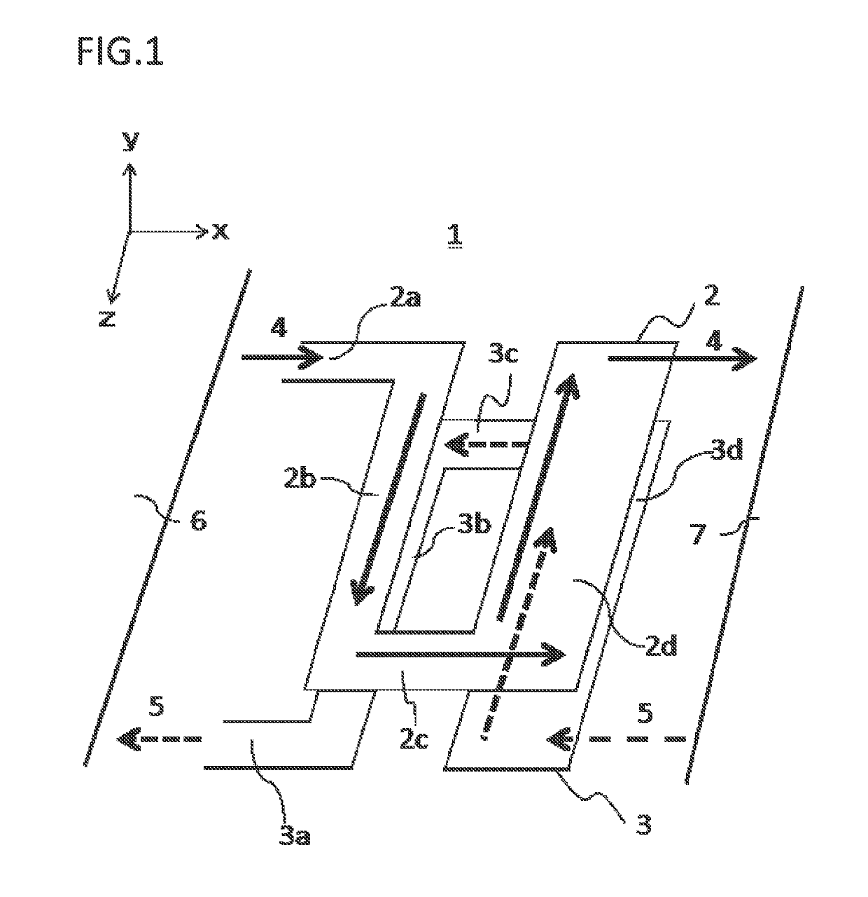
[0058]FIG. 1 is a perspective view showing the structure of a bus bar according to embodiment 1 of the present invention. In FIG. 1, a bus bar structure 1 is provided between a first device 6 and a second device 7 arranged side by side in an x-axis direction. In the bus bar structure 1, an upper bus bar 2 and a lower bus bar 3 are arranged so as to be opposed to each other in a y-axis direction perpendicular to the x-axis direction. A direction perpendicular to both of the x-axis direction and the y-axis direction is defined as a z-axis direction. In the drawings, an arrow direction of each of the x axis, the y axis, and the z axis is defined as a positive direction, and the direction opposite thereto is defined as a negative direction. Here, the upper bus bar 2 and the lower bus bar 3 are both made of a conductor such as metal.
[0059]The upper bus bar 2 is composed of: a first end 2a which is connected to the first device 6 and through which current 4 is introduced; a first connecti...
embodiment 2
[0084]In embodiment 1 of the present invention, as shown in FIG. 6 to FIG. 9, the first end 2a and the second end 3a are formed to be opposed to each other in the z-axis direction, between the upper bus bar 2 and the lower bus bar 3. In embodiment 2 of the present invention, as shown in FIG. 10A, current is introduced or led out directly from the ends of the first connection portion 2b and the third connection portion 3b.
[0085]That is, in FIG. 10A, lead-out portions that are current introduction portions are the entire z-axis-direction end surfaces of the first connection portion 2b and the second connection portion 3b. In the shown example, a width 30a and a width 30b in the z-axis direction are set to be equal to each other. However, these widths may not necessarily be equal to each other, that is, the width 30a in the z-axis direction may be greater than the width 30b, or the width 30a in the z-axis direction may be smaller than the width 30b. FIG. 10B shows a part of short-circ...
embodiment 3
[0086]FIG. 11A is a perspective view of a bus bar structure according to embodiment 3 of the present invention. In embodiment 3 of the present invention, as shown in FIG. 11A, a third end 2e of the upper bus bar 2 and a fourth end 3e are arranged so as to be opposed to each other in the z-axis direction. The third end 2e and the fourth end 3e are connected to the power module 17 (not shown). The entire upper bus bar 2 and the entire lower bus bar 3 have a constant width 22c. It is desirable that the constant width 22c is about six times the skin thickness as described above.
[0087]As in the embodiments described thus far, as shown in FIG. 11B, a one-turn loop 29 of a short-circuit current path is formed by the upper bus bar 2 and the lower bus bar 3. In order to increase the inductance, conventionally, a coil is wound and the coil is connected or sandwiched between the bus bars. However, an inductance increasing effect can be obtained by a simple configuration in which the bus bars a...
PUM
 Abstract
Description
Claims
Application Information