Gear change device

a gear change and gear technology, applied in the direction of gearing control, mechanical equipment, transportation and packaging, etc., can solve the problems of increasing the weight of the device as a whole, the durability of the ball-screw mechanism or the gear mechanism, and the durability and the operation speed of the electric motor, etc., to achieve excellent durability and high operation speed

Inactive Publication Date: 2005-04-12
ISUZU MOTORS LTD
View PDF12 Cites 11 Cited by
  • Summary
  • Abstract
  • Description
  • Claims
  • Application Information

AI Technical Summary

Benefits of technology

It is an object of the present invention to provide a gear change device equipped with a select actuator which features excellent durability and a high operation speed.

Problems solved by technology

The select actuator and the shift actuator using the fluid pressure cylinders require piping connecting the source of fluid pressure to the actuators, an electromagnetic change-over valve for changing over the flow passage of the operation fluid, and space for the arrangement thereof, resulting in an increase in the weight of the device as a whole.
However, the actuators using a ball-screw mechanism or a gear mechanism are not necessarily satisfactory in regard to the durability of the ball-screw mechanism and the gear mechanism and in regard to the durability and the operation speed of the electric motor.

Method used


Image

  • Gear change device
  • Gear change device
  • Gear change device

Examples


first embodiment

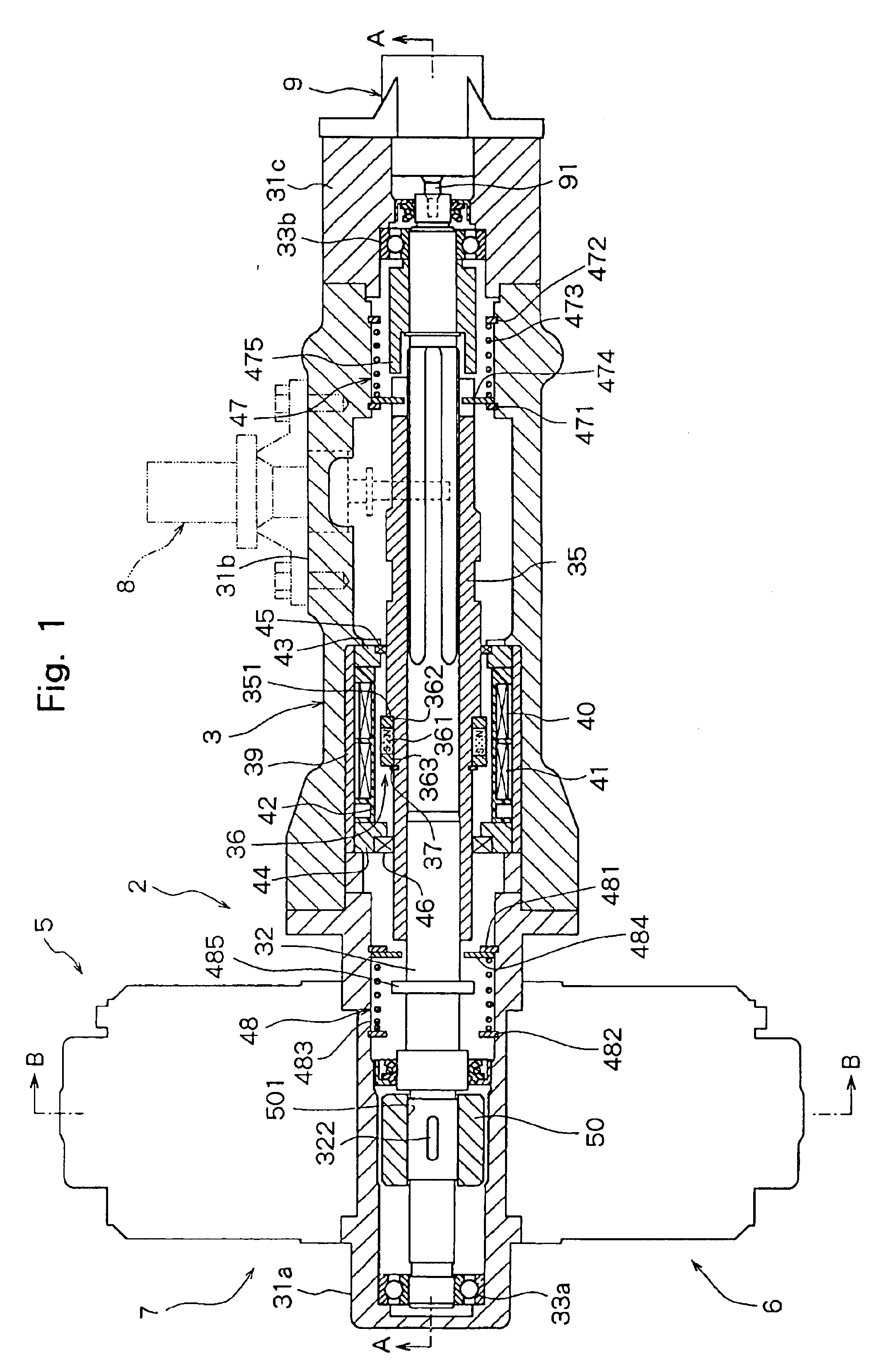
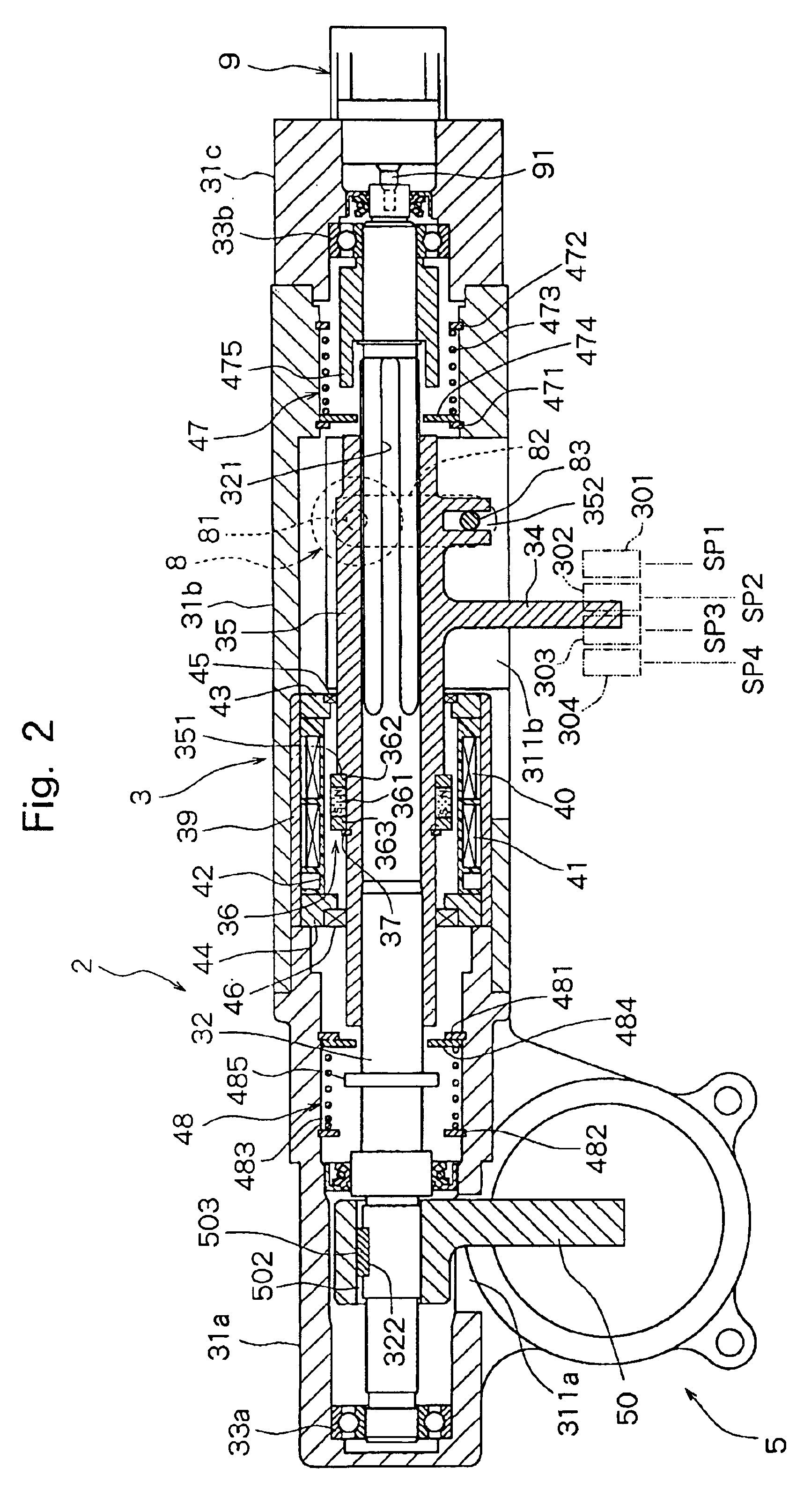
The select actuator 3 is constituted as described above, and works based on a principle of a linear motor that is constituted by the magnetic moving means 36 disposed on the shift sleeve 35 that serves as the shift lever support member, by the fixed yoke 39 and by the pair of coils 40 and 41. The operation will now be described with reference to FIGS. 4A and 4B.

In the select actuator 3 according to the first embodiment, there is established a magnetic circuit 368 passing through the N-pole of permanent magnet 361, one moving yoke 362, one coil 40, fixed yoke 39, the other coil 41, the other moving yoke 363 and S-pole of permanent magnet 361, as shown in FIGS. 4A and 4B. In this state, when electric currents are supplied to the pair of coils 40 and 41 in the directions opposite to each other as shown in FIG. 4A, a thrust toward the right is produced by the magnetic moving means 36, i.e., produced by the shift sleeve 35, as indicated by an arrow in FIG. 4A, due to the Fleming's left-...

second embodiment

The select actuator 3a is constituted by one coil 40a disposed on the inside of the fixed yoke 39. The length of the coil 40a in the axial direction is set to be nearly the same as the length of selection from the first select position SP1 to the fourth select position SP4.

The magnetic moving means 36a comprises a moving yoke 360a mounted on the outer peripheral surface of the shift sleeve 35 which is the shift lever support member, and an annular permanent magnet 364a disposed on the outer peripheral surface of the moving yoke 360a facing the inner peripheral surface of the coil 40a. The moving yoke 360a is made of a magnetic material, and has a cylindrical portion 361a, on which a permanent magnet 364a is mounted, and annular flanges 362a and 363a provided at both ends of the cylindrical portion 361a. The outer peripheral surfaces of the flanges 362a and 363a are close to the inner peripheral surface of the fixed yoke 39. It is desired that the gap between the outer peripheral su...

third embodiment

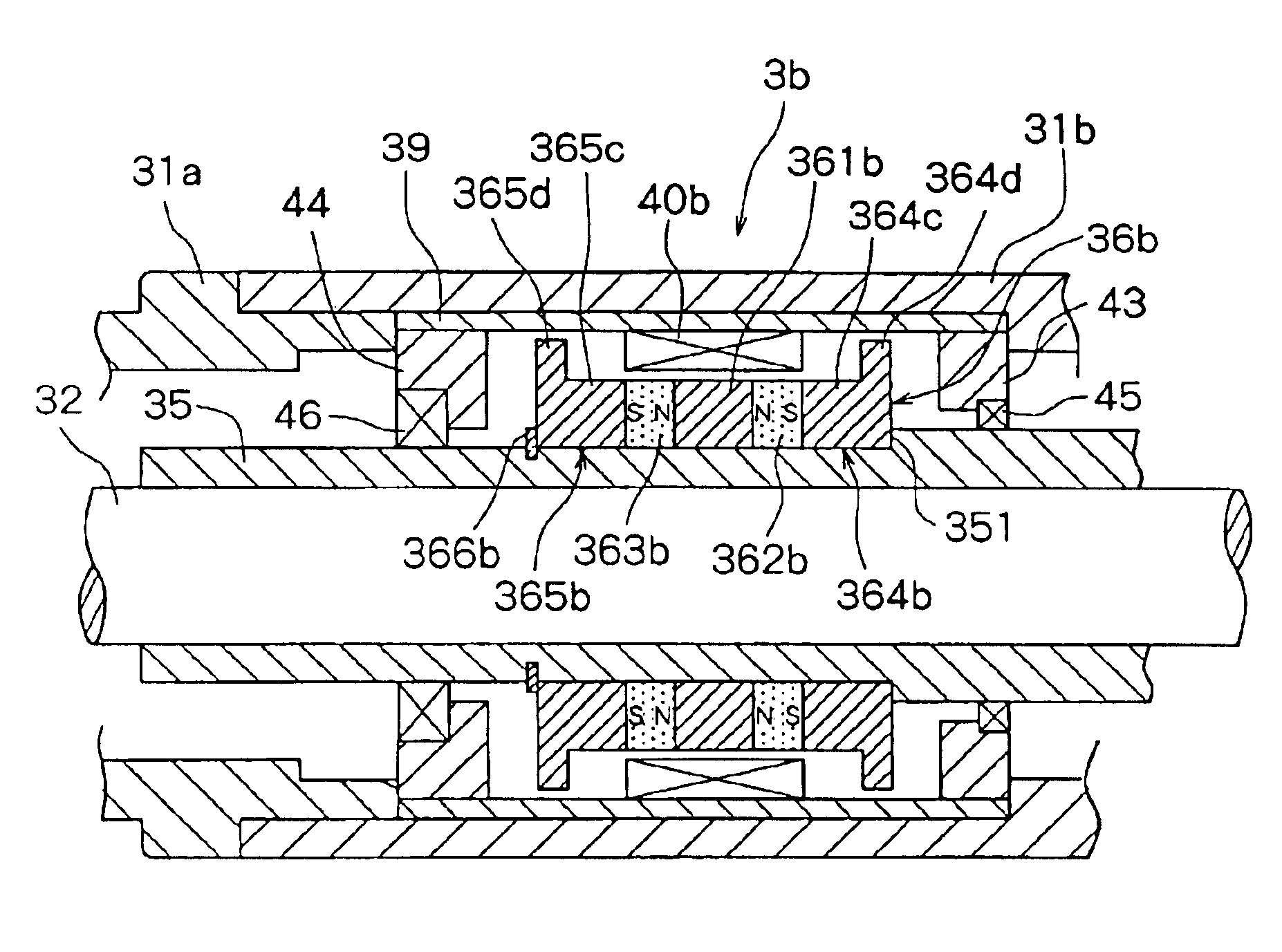
The select actuator 3b is constituted as described above. The operation will now be described with reference to FIGS. 8A and 8B.

In the select actuator 3b of the third embodiment as shown in FIGS. 8A and 8B, a first magnetic flux circuit 368b and a second magnetic flux circuit 369b are formed by the pair of permanent magnets 362b and 363b. That is, in the select actuator 3b of the illustrated embodiment, there are established the first magnetic circuit 368b passing through the N-pole of permanent magnet 362b, intermediate yoke 361b, coil 40b, fixed yoke 39, flange 364d of the moving yoke 364b, cylindrical portion 364c of the moving yoke 364b and S-pole of the permanent magnet 362b, and the second magnetic circuit 369b passing through the N-pole of permanent magnet 363b, intermediate yoke 361b, coil 40b, fixed yoke 39, flange 365d of the moving yoke 365b, cylindrical portion 365c of the moving yoke 365b and S-pole of the permanent magnet 363b. When in this state, an electric current ...


PUM


Abstract

A gear change device includes a select actuator for operating a shift lever in a direction of selection and a shift actuator for operating the shift lever in a direction of shift. The select actuator includes a casing, a shift lever support member that is disposed in the casing so as to slide in an axial direction. The shift lever support member supports the shift lever, a magnetic moving member disposed on the outer periphery of the shift lever support member, a cylindrical fixed yoke surrounding the magnetic moving member, and a coil disposed on the inside of the fixed yoke.

Description

FIELD OF THE INVENTIONThe present invention relates to a gear change device for shifting a transmission mounted on a vehicle.DESCRIPTION OF THE RELATED ARTA gear change device for shifting a transmission comprises a select actuator for operating a shift lever in the direction of selection and a shift actuator for operating the shift lever in the direction of shift.As the select actuator and the shift actuator, there have generally been used fluid pressure cylinders which provide fluid under pressure, such as air under pressure or hydraulic fluid under pressure, as a source of actuation. The select actuator and the shift actuator using the fluid pressure cylinders require piping connecting the source of fluid pressure to the actuators, an electromagnetic change-over valve for changing over the flow passage of the operation fluid, and space for the arrangement thereof, resulting in an increase in the weight of the device as a whole.In recent years, there have been proposed a select ac...

Claims


Application Information

Patent Timeline
Patent Type & Authority Patents(United States)
IPC IPC(8): F16H61/28F16H61/32F16H63/24H02K33/12
CPCF16H61/32F16H2061/2853Y10T74/20177Y10T74/2003Y10T74/19251
Inventor YAMAMOTO, YASUSHI
Owner ISUZU MOTORS LTD
Why Eureka
Try Eureka