

Multi-stage projectile weapon for immobilization and capture
a projectile and multi-stage technology, applied in the field of non-lethal weapons, can solve the problems of not being able to clear the wiring from the firearm's bore after the projectile, the length of the wires that can be stored in the casing or the projectile constitutes a still severe distance limitation for the projectile travel from the launcher,
- Summary
- Abstract
- Description
- Claims
- Application Information
AI Technical Summary
Benefits of technology
Problems solved by technology
Method used
Image

Examples
Embodiment Construction
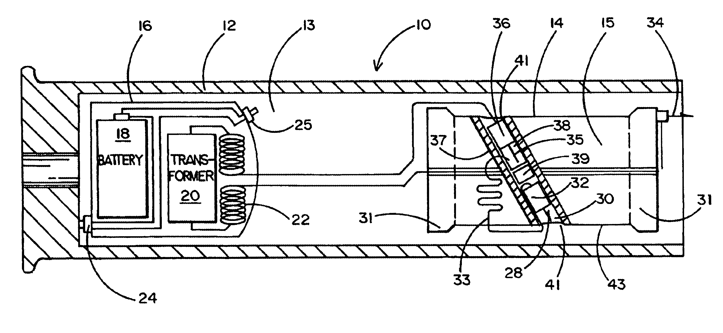
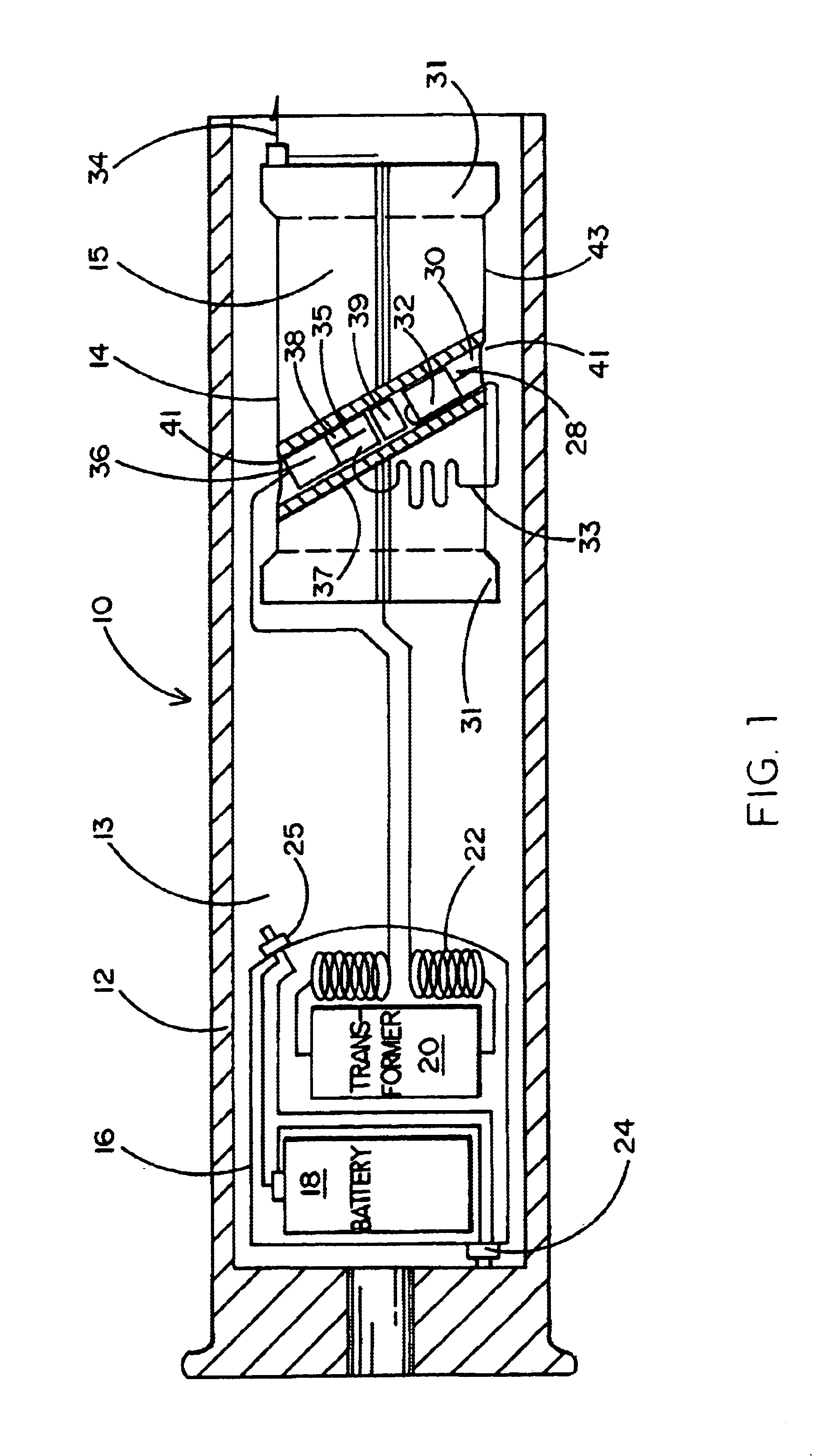
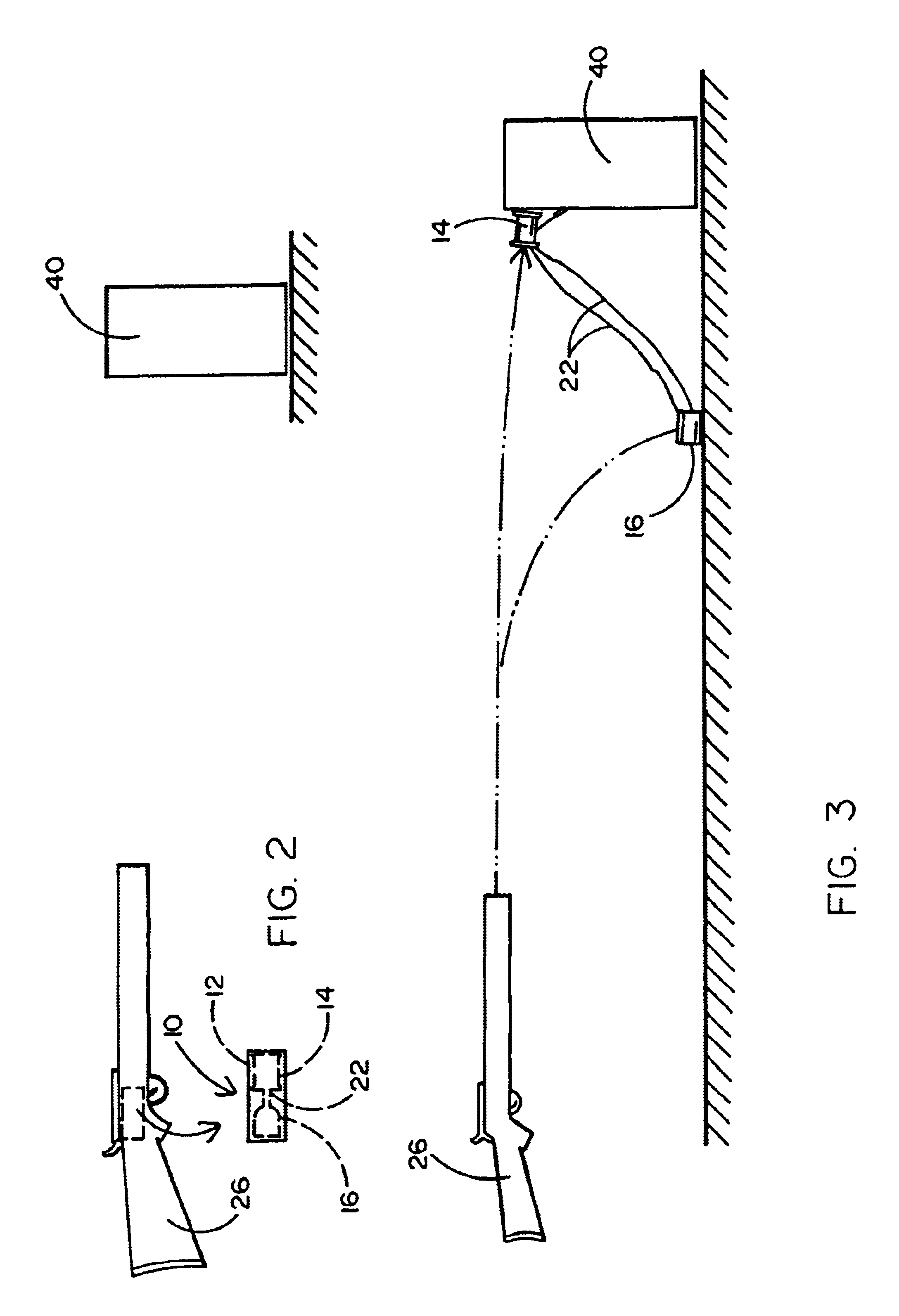
Referring to the accompanying drawings and initially to FIG. 1 in particular, it will be seen that an exemplary embodiment of a multistage projectile 10 is shown therein. Projectile 10 comprises a case 12 forming a hollow cylindrical interior chamber 13. Within chamber are positioned a first stage projectile 14 and a second stage projectile 16.
First stage projectile 14 is configured and functions in the manner described in the disclosure of issued U.S. Pat. No. 5,831,199 the content of which is hereby expressly incorporated herein by reference as if fully set forth herein. For purposes of convenience it will be observed that the principal features of first stage projectile 14 are shown herein in FIG. 1. More specifically, it will be seen that projectile 14 comprises a generally cylindrical body 15 having end caps 31 and having an intermediately located metalized diagonal passage 30. Within passage lies a connector body 32 terminating in a connector 28. Also within passage 30 and beh...
PUM
 Abstract
Description
Claims
Application Information