
Drilling with casing

a casing and drilling technology, applied in the direction of drilling pipes, rotary drilling, directional drilling, etc., can solve the problems of limited acceptance of casing drilling operations, high cost of casing capable of transmitting high torque from the surface to the bit, and damage to the upper formation

Inactive Publication Date: 2005-04-12
HALLIBURTON ENERGY SERVICES INC
View PDF14 Cites 31 Cited by
  • Summary
  • Abstract
  • Description
  • Claims
  • Application Information

AI Technical Summary

Benefits of technology

An advantage of the present invention is that the bottom hole assembly does not require especially made components. Each of the components of the bottom hole assembly may be selected by the operator as desired to achieve the objectives of the invention.
is that the bottom hole assembly does not require especially made components. Each of the components of the bottom hole assembly may be selected by the operator as desired to achieve the objectives of the invention.

Problems solved by technology

The depth of each drilled section is thus a function of (1) the operator's desire to continue drilling as deep as possible prior to stopping the drilling operation and inserting the casing in the drilled section, (2) the risk that upper formations will be damaged by high pressure fluid required to obtain the desired well balance and downhole fluid pressure at greater depths, and (3) the risk that a portion of the drilled well may collapse or otherwise prevent the casing from being run in the well, or that the casing will become stuck in the well or otherwise practically be prevented from being run to the desired depth in a well.
Problems have nevertheless limited the acceptance of casing drilling operations, including the cost of casing capable of transmitting high torque from the surface to the bit, high losses between the surface applied torque and the torque on the bit, high casing wear, and difficulties associated with retrieving the bit and the drill motor to the surface through the casing.

Method used


Image

  • Drilling with casing
  • Drilling with casing
  • Drilling with casing

Examples


Embodiment Construction

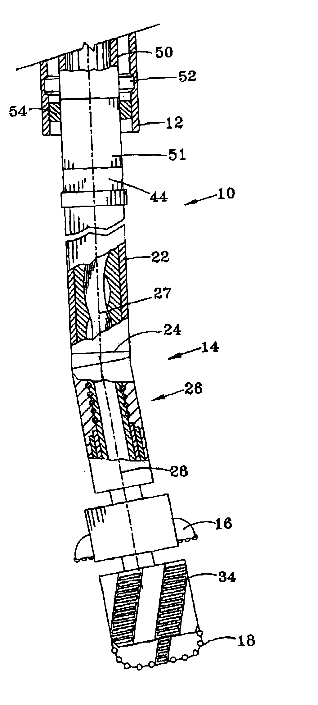
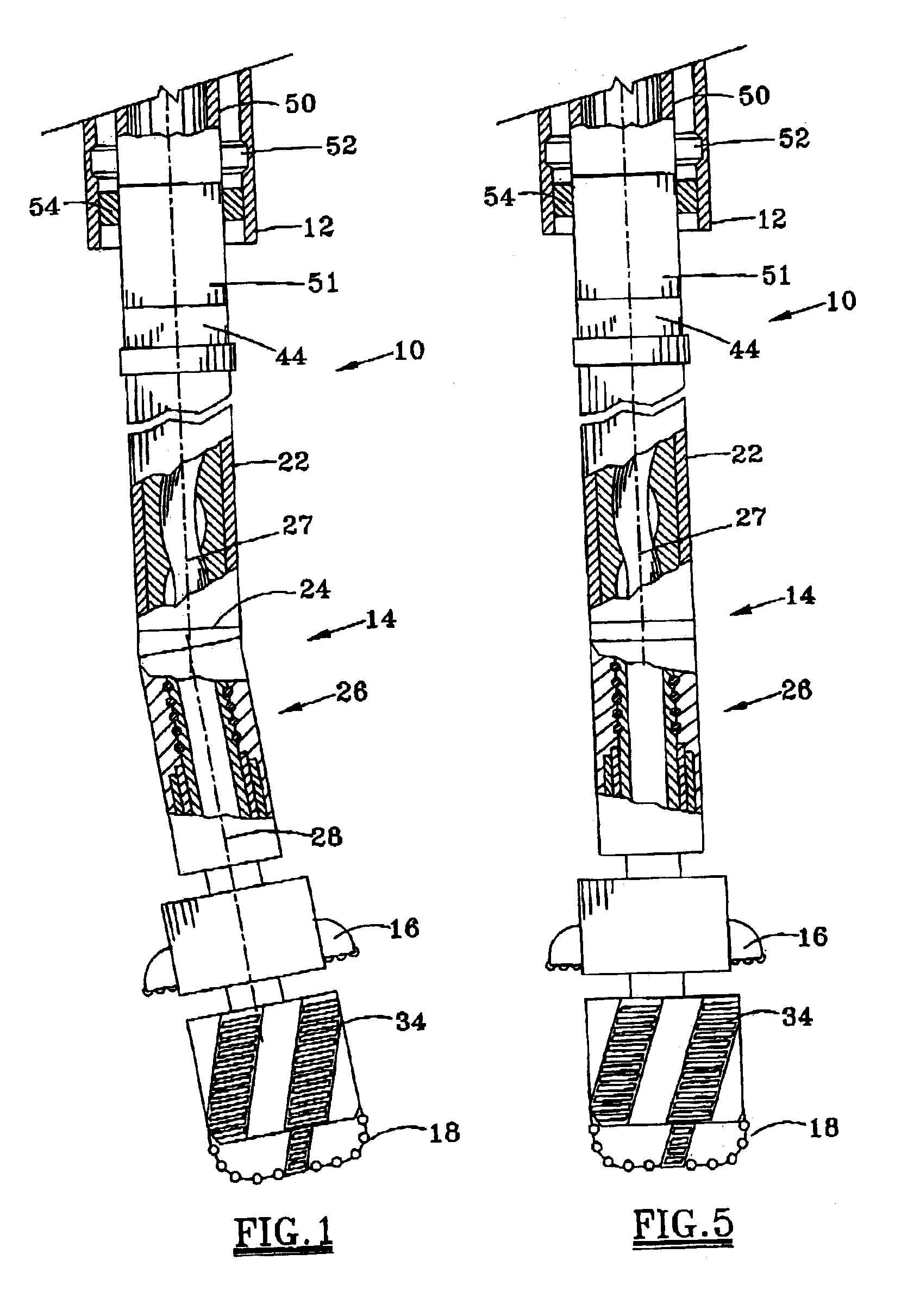
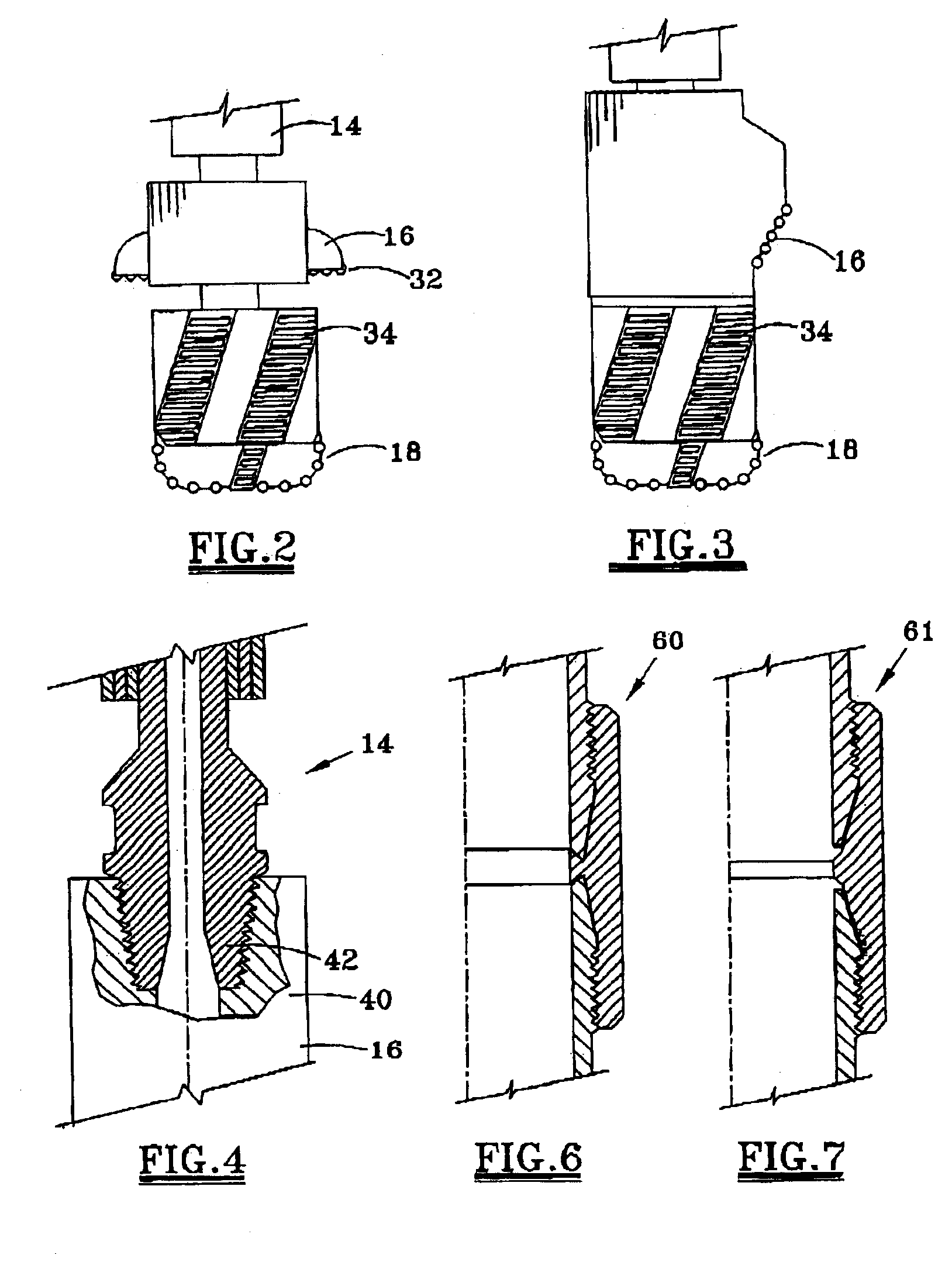
FIG. 1 generally illustrates a well drilled with a bottom hole assembly (BHA) 10 at the lower end of a casing string 12. The BHA 10 includes a fluid powered downhole motor 14 with a bend for rotating a bit 16 to drill a deviated portion of the well. A straight section of the well may be drilled by additionally rotating the casing string 12 at the surface to rotate the bit 16, which as explained subsequently may be either a reamer or a bi-centered bit. To drill a curved section of the borehole, the casing is slid (non-rotating) and the downhole motor 14 rotates the bit 16. It is generally desirable to rotate the casing string to minimize the likelihood of the casing string becoming stuck in the borehole, and to improve return of cuttings to the surface. In the preferred embodiment, a bend in the bottom hole assembly has a bend angle of less than about 3°.

Since the bit 16 which drills the borehole has a cutting diameter greater than the OD of the casing, and since the bit is retrieved...


PUM


Abstract

A borehole may be drilled utilizing the bottom hole assembly 10, 50 with a downhole motor 14, which may offset at a selected bend angle. The motor housing is preferably run slick, and a gauge section 36 secured to the pilot bit 18 has a uniform diameter bearing surface along an axial length of at least 60% of the pilot bit diameter. The bit or reamer 16 has a bit face defining the cutting diameter of the drilled hole. The axial spacing between the bend and the bit face is controlled to less than fifteen times the bit diameter. The downhole motor, pilot bit and bit may be retrieved from the well while leaving the casing string in the well.

Description

FIELD OF THE INVENTIONThe present invention relates to technology for drilling an oil or gas well, with the casing string remaining in the well after drilling. More particularly, the present invention relates to techniques for improving the efficiency of drilling a well with casing, with improved well quality providing for enhanced hydrocarbon recovery, and with the technology allowing for significantly reduced costs to reliably complete the well.BACKGROUND OF THE INVENTIONMost hydrocarbon wells are drilled in successively lower casing sections, with a selected size casing run in a drilled section prior to drilling the next lower smaller diameter section of the well, then running in a reduced diameter casing size in the lower section of the well. The depth of each drilled section is thus a function of (1) the operator's desire to continue drilling as deep as possible prior to stopping the drilling operation and inserting the casing in the drilled section, (2) the risk that upper for...

Claims


Application Information

Patent Timeline
Patent Type & Authority Patents(United States)
IPC IPC(8): E21B17/00E21B17/08E21B17/10E21B7/04E21B7/06E21B17/02E21B7/20E21B10/26
CPCE21B7/067E21B7/20E21B17/1092E21B17/08E21B10/26E21B7/203E21B7/068
Inventor CHEN, CHEN-KANG D.RAO, M. VIKRAM
Owner HALLIBURTON ENERGY SERVICES INC
Learn More