Rear suspension connecting part structure under the floor of a vehicle

a technology for connecting parts and vehicles, applied in steering links, pivoted suspension arms, transportation and packaging, etc., can solve the problems of increased manufacturing costs, increased production costs, and increased production costs, so as to reduce the number of parts required, reduce the weight of the rear suspension connecting structure, and reduce the manufacturing and assembly cost of the vehicle.

Inactive Publication Date: 2005-04-12
HYUNDAI MOTOR CO LTD
View PDF17 Cites 19 Cited by
  • Summary
  • Abstract
  • Description
  • Claims
  • Application Information

AI Technical Summary

Benefits of technology

The present invention provides a rear suspension connecting structure for a vehicle adapted to reduce the number of parts required and the manufacturing and assembly cost of the vehicle. Furthermore, the present invention reduces the weight of the rear suspension connecting structure, while maintaining sufficient strength.

Problems solved by technology

A drawback in the conventional structure is that there is such a plurality of components that the cost of manufacture is increased, excessive manufacture time is lost, excessive resources are expanded and the weight of the vehicle is increased.
Another drawback is that the bolts, for coupling the cross member and the rear floor side member are mounted to relatively short welded nuts.
The short nuts result in the shank of the bolts not being stably held.

Method used


Image

  • Rear suspension connecting part structure under the floor of a vehicle
  • Rear suspension connecting part structure under the floor of a vehicle
  • Rear suspension connecting part structure under the floor of a vehicle

Examples


Embodiment Construction

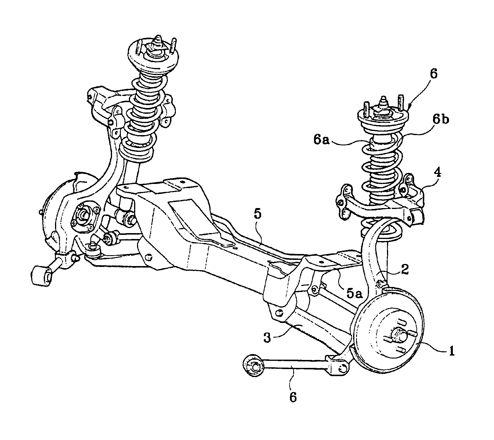
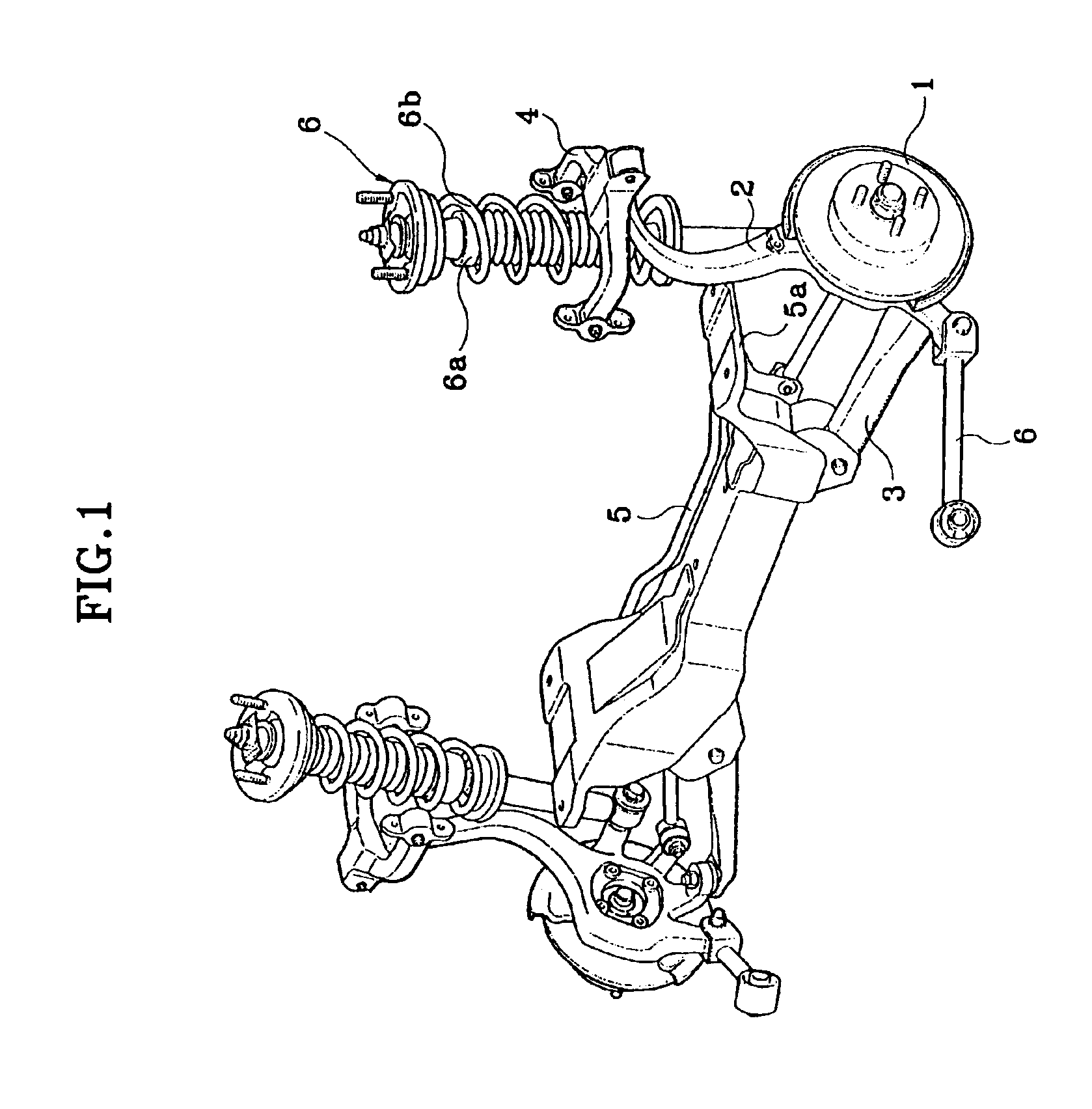
As shown in FIG. 1, a typical rear suspension connecting structure includes generally a cross member that interconnects the wheel attaching components, brake components, and the suspension.

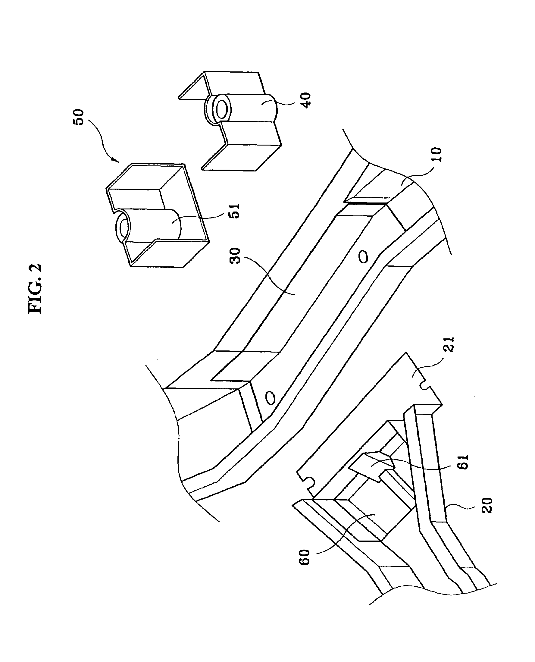
Referring to FIGS. 2 and 3, a rear suspension connecting structure that connects under the floor of a vehicle according to an embodiment of the invention includes a rear floor side member 10 that defines each end of the floor panel rear portion (not shown). A rear floor cross member 20 is included and connects to the rear floor side member 10. A first reinforcement 30 is welded to an inner floor surface of the rear floor side member 10. Weld pipe 40 is welded to the front and rear part of the reinforcement 30. The weld pipe 40 also has female screw threads for receiving a bolt. A vertical bulkhead 50 is configured to encompass one side of the weld pipe 40 and positioned within the rear floor side member 10. Also, a second reinforcement 60 is coupled to an inner surface of the rear floor cross memb...


PUM


Abstract

A rear suspension connecting structure located under the floor of a vehicle wherein one horizontal reinforcement member is employed at an inner side of the rear floor side member. A weld pipe, for receiving an entire shank of a bolt, is coupled to an upper side of the reinforcement, and the weld pipe is coupled to a vertical bulkhead coupled along the width of the reinforcement.

Description

FIELD OF THE INVENTIONThe present invention relates to the rear suspension of a vehicle. More particularly, the present invention relates to the rear suspension connecting and support structure of a vehicle.BACKGROUND OF THE INVENTIONConventional rear wheel assemblies of a vehicle include rear suspension components and hub and brake assemblies. Furthermore, knuckles attach the hub and brake assemblies to the vehicle and to a cross member. The cross member is typically mounted with the floor of the vehicle.The floor of the vehicle is typically configured with a rear floor side member that is coupled to a rear floor cross member. A reinforcement piece is coupled inside the rear floor side member and to the floor of the vehicle. A second reinforcement is coupled to the reinforcement piece. Nuts, welded to square brackets are used to hold the components together and the square brackets are then welded to the second reinforcing member. Furthermore, a third reinforcement is welded on top ...

Claims


Application Information

Patent Timeline
Patent Type & Authority Patents(United States)
IPC IPC(8): B62D21/11B62D25/20B62D25/08
CPCB62D21/11B62D25/087B60G2206/602B60G2204/43B60G2204/15B60G2202/312B60G2200/1442B60G2206/0114B60G2204/143B62D25/20
Inventor KIM, KI-CHANG
Owner HYUNDAI MOTOR CO LTD
Why Eureka
Try Eureka