Protector for wire harnesses and mounting mechanism

Inactive Publication Date: 2005-04-12
HONDA MOTOR CO LTD
View PDF7 Cites 27 Cited by
  • Summary
  • Abstract
  • Description
  • Claims
  • Application Information

AI Technical Summary

Benefits of technology

The object of the present invention is to provide a protector for wire harnesses and a mounting mechanism therefor, which enable smooth attachment of the protector to receiving elements even if they are relatively displaced.
The present invention provides a protector for wire harnesses including a body with closed cross section through which the wire harnesses are routed and at least two mounting elements by which the protector is attached to receiving elements. The protector has a feature that position adjustment means including a flexible portion is provided in the body extending between the two mounting elements so that a relative position of the two mounting elements can be adjusted.
In this way, even if the positions of receiving elements are displaced, the arrangement described above, which enables the adjustment of relative position of two mounting elements, allows an easy attachment of the protector. It can also prevent a large amount of load from acting on the mounting and receiving elements.
If the position adjustment means includes at least a slit, the resultant simple

Problems solved by technology

Receiving elements are not necessarily positioned accurately with respect to each other due to errors associated with assembly and manufacturing.
When one of the mounting elements of a protector is mated with one of the receiving elements, it may have the problem that a relative displacement between the other mounting element and the other receiving element occurs so that the protector cannot be smoothly attached.
Even

Method used


Image

  • Protector for wire harnesses and mounting mechanism
  • Protector for wire harnesses and mounting mechanism
  • Protector for wire harnesses and mounting mechanism

Examples


Example

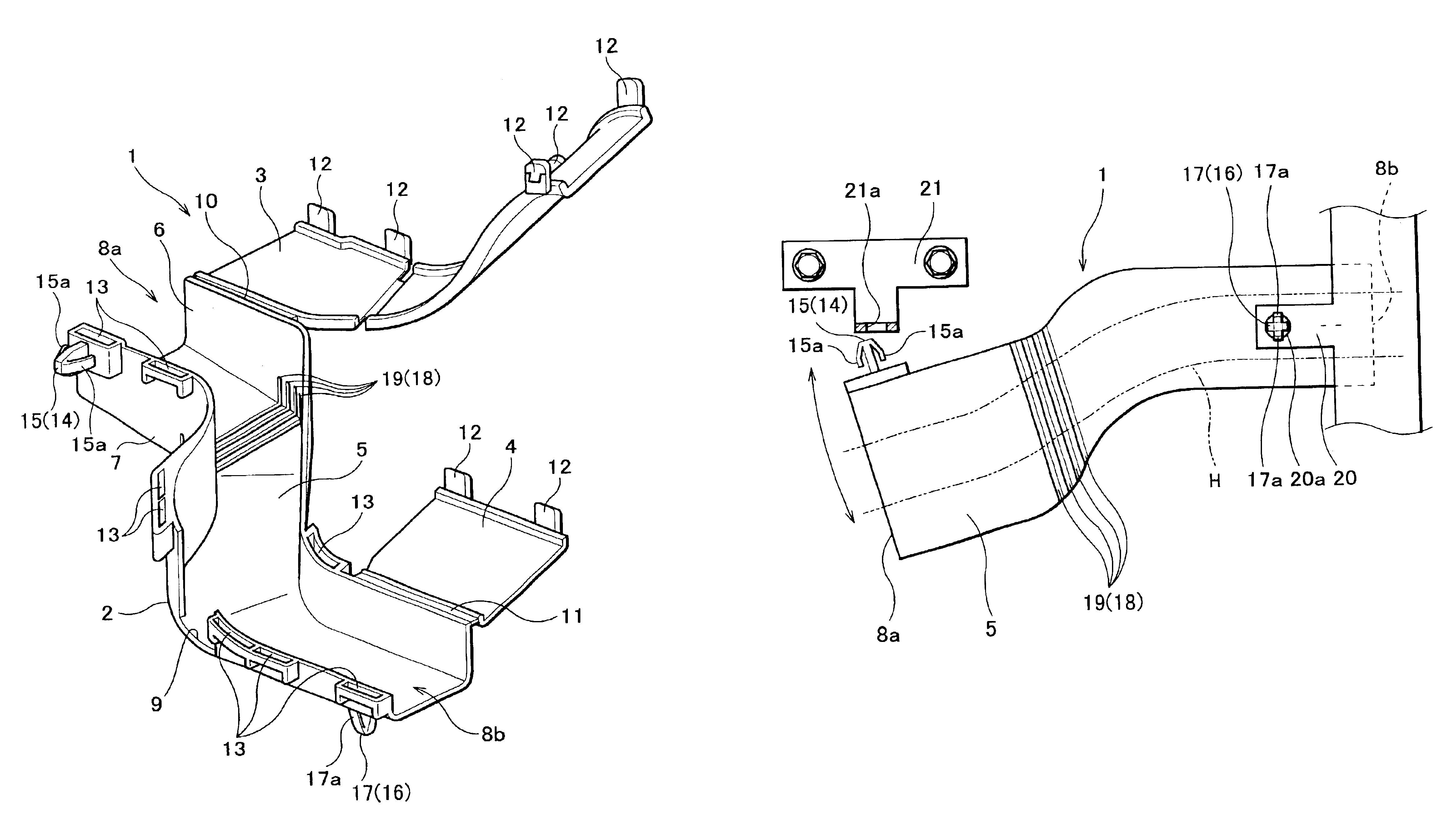
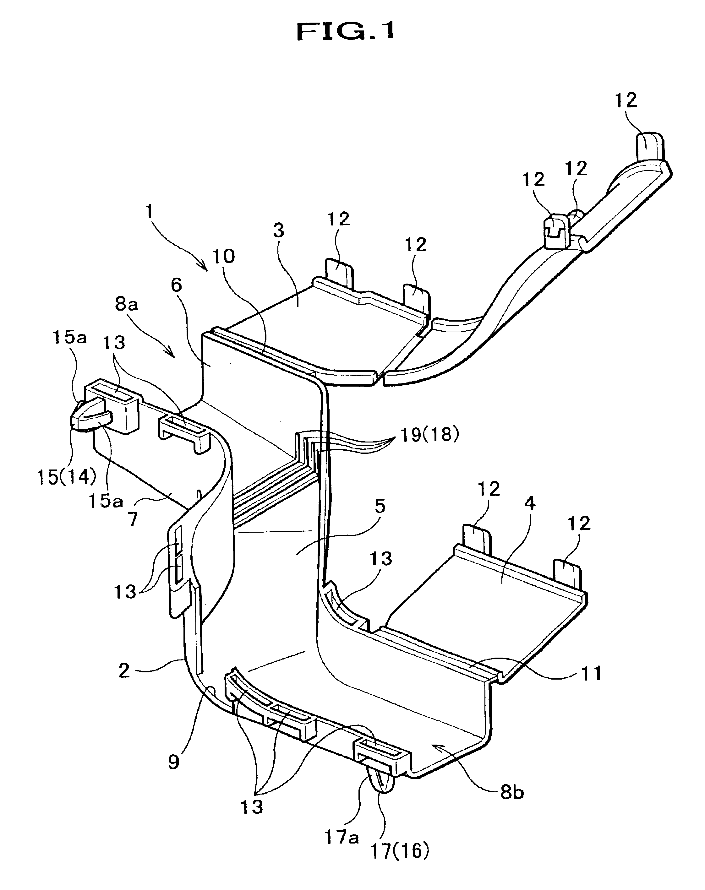
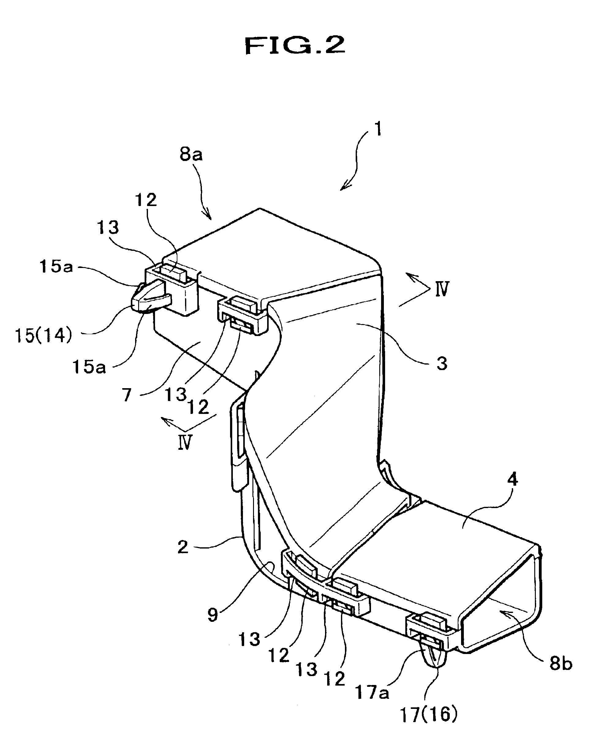
An embodiment of the present invention will now be described with reference to the accompanying drawings. FIGS. 1 and 2 are perspective views showing a protector for wire harnesses. FIG. 1 is a view showing the protector with opened first and second covers and FIG. 2 is a view showing the protector with closed first and second covers. FIG. 3 is a side view illustrating attachment of the protector and FIG. 4 is a sectional view taken along line IV—IV shown in FIG. 2.

A protector 1 for wire harnesses (hereinafter referred to as a protector), which is for protecting wire harnesses H (see FIGS. 3 and 4) typically routed in an open space, has a closed cross section, to be described later, so that the protector 1 can cover 360 deg. around the wire harnesses H.

The protector 1, which is a casing made of a flexible synthetic resin such as polypropylene, comprises a base portion 2, a first cover 3 and a second cover 4. The base portion 2 includes a base plate 5 extending in a direction of rout...


PUM

PropertyMeasurementUnit
Fractionaaaaaaaaaa
Flexibilityaaaaaaaaaa

Abstract

A protector for wire harnesses and mounting mechanism are provided, including a body with closed cross section through which the wire harnesses are routed and at least two mounting elements by which the protector is attached to receiving elements. The protector has a feature that a position adjuster including a flexible portion is provided in the body extending between the two mounting elements so that a relative position of the two mounting elements can be easily adjusted.

Description

FIELD OF THE INVENTIONThe present invention relates to a protector for wire harnesses.BACKGROUND OF THE INVENTIONA protector has usually been employed for protection of wire harnesses, which are routed behind an instrument panel of a vehicle and the like. When wire harnesses are routed along a mounting surface, a protector having U-shaped cross section is used to cover them, for example. In this case, the wire harnesses are covered by the three surfaces of the protector and the mounting surface, which serves as the fourth surface to make a closed surrounding.The wire harnesses, which are installed behind an instrument panel, are often routed not along a mounting surface but in a space provided behind the instrument panel. In this case, a protector having a closed cross section is typically used, which covers 360 deg. around the wire harnesses. A protector of this type, which normally has at least two mounting elements which are mated with given receiving elements, is fixed by them.R...

Claims


Application Information

Patent Timeline
IPC IPC(8): H02G3/02H02G3/06H02G3/04H02G3/30H02G3/38
CPCH02G3/0418H02G3/0608H02G3/0437
Inventor TAKAHASHI, SHIGEKIMURO, SHINTARO
Owner HONDA MOTOR CO LTD
Why Eureka
Try Eureka