Connecting component

Active Publication Date: 2013-06-27
JAPAN AVIATION ELECTRONICS IND LTD
View PDF5 Cites 0 Cited by
  • Summary
  • Abstract
  • Description
  • Claims
  • Application Information

AI Technical Summary

Benefits of technology

[0008]An object of the present invention is to overcome the above problems in the art and provide a connecting component

Problems solved by technology

Thus, the up-turned portions of the tips of the connector connection terminals 6 form stubs that deteriorate high frequency char

Method used


Image

  • Connecting component
  • Connecting component
  • Connecting component

Examples


Example

Embodiment 1

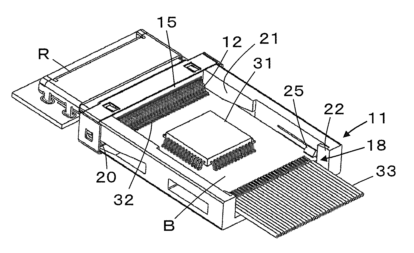
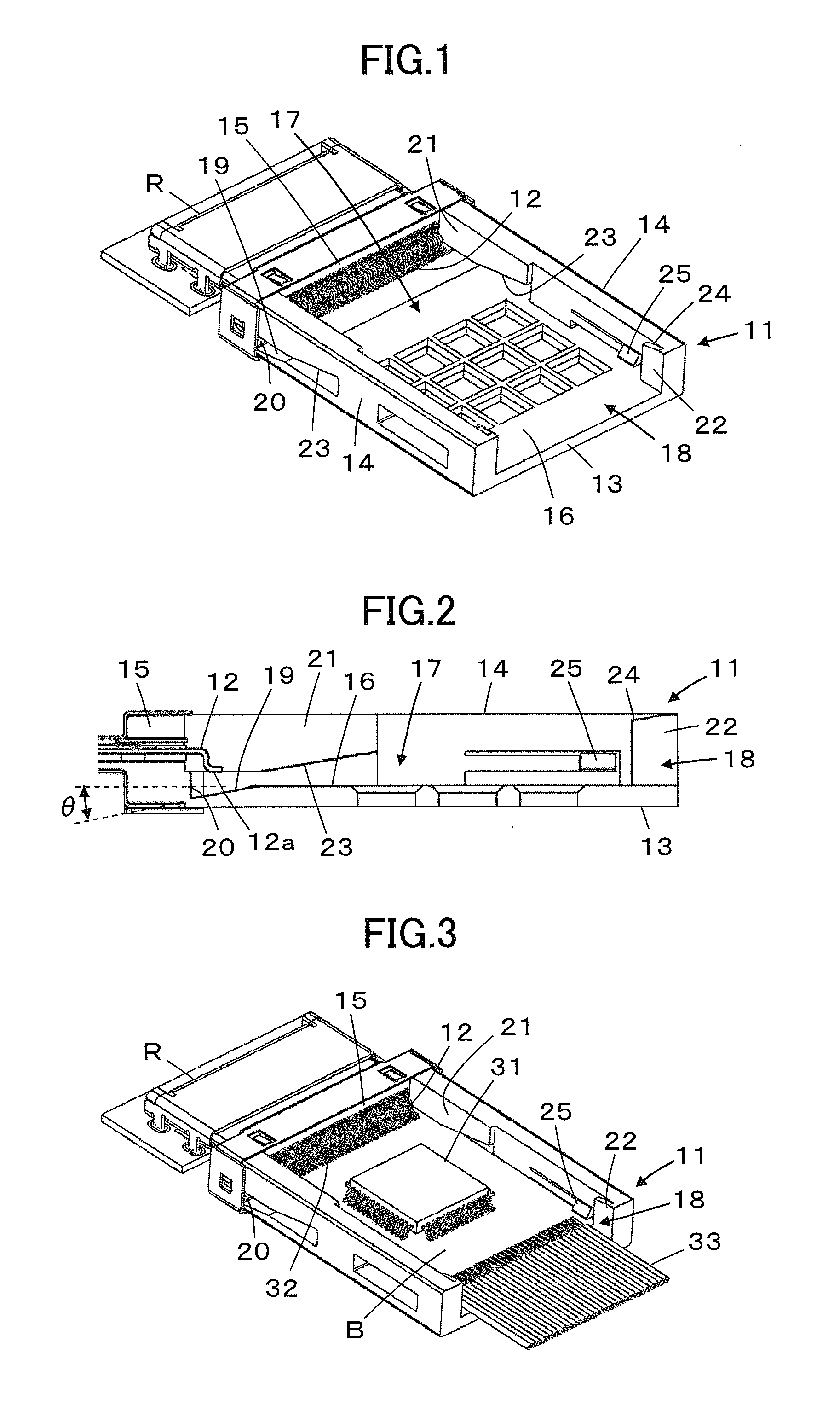
[0027]FIGS. 1 and 2 illustrate a configuration of a connecting component according to Embodiment 1 of the invention. The connecting component constitutes a part of a plug connector part of a pair of connector parts connected to each other and comprises a housing 11 shaped generally like a tray and a plurality of housing connection terminals 12 secured to the housing 11.

[0028]The housing 11 comprises a rectangular base portion 13 having a pair of longer sides and a pair of shorter sides, a pair of upright side walls 14 provided opposite each other along the longer sides of the base portion 13, and an end wall 15 erected along one of the pair of the shorter sides of the base portion 13 and connected with both the side walls 14. A top surface 16 of the base portion 13 is surrounded on three sides by the pair of side walls 14 and the end wall 15, forming a recessed containing portion 17 for a subsidiary board. On the other shorter side of the base portion 13 opposite the end...

Example

Embodiment 2

[0051]While the connecting component according to Embodiment 1 is adapted to attach a subsidiary board to a plug connector part, a connecting component is used to attach a subsidiary board to a main board in Embodiment 2. FIG. 9 illustrates a connecting component according to Embodiment 2.

[0052]The connecting component comprises a housing 41 secured to a main board P and housing connection terminals 12 connected to the housing 41.

[0053]The housing 41 comprises support members 42 placed in contact with the top surface of the main board P to support the housing 41 but otherwise has the same configuration as the housing 11 of the connecting component according to Embodiment 1. Thus, the top surface 16 of the base portion 13 is surrounded on three sides by the pair of side walls 14 and the end wall 15, forming the subsidiary board containing portion 17 having a recessed shape. The remaining one side of the top surface 16 of the base portion 13 has the opening 18. The first s...

Example

Embodiment 3

[0058]FIG. 14 illustrates a connecting component according to Embodiment 3. The connecting component is the same as one according to Embodiment 2 illustrated in FIG. 9 except for the housing 41 being divided into two members.

[0059]The connecting component comprises a housing 41a secured to the main board P, the housing connection terminals 12 connected to the housing 41a, and an auxiliary member 41b detachably attached to the housing 41a.

[0060]The housing 41a comprises a base portion 13a, a pair of side walls 14a, and the end wall 15. The first slope 19 is formed on a top surface 16a on the side of the base portion 13a closer to the end wall 15. The bosses 21 are formed on the pair of the side walls 14a near the end wall 15. The bosses 21 each have the second slopes 23 formed on the lower surfaces thereof. The wall surface of the end wall 15 forms the abutment 20. The side walls 14a each have the support member 42 on the outside thereof.

[0061]The auxiliary member 41b co...


PUM


Abstract

A connecting component includes a housing, housing connection terminals secured to the housing, an abutment located beneath the housing connection terminals, a first guide portion located beneath the housing connection terminals for regulating a position of a bottom surface of the subsidiary board, second guide portions located in front of the first guide portion as seen in a subsidiary board insertion direction for regulating the top surface of the subsidiary board, and third guide portions located in front of the first guide portion as seen in the subsidiary board insertion direction on a straight line passing through the first guide portion and the second guide portions and disposed in a position away from the abutment by a distance longer than an overall length of the subsidiary board, the third guide portions regulating the position of the bottom surface of the subsidiary board.

Description

BACKGROUND OF THE INVENTION[0001]The present invention relates to a connecting component and in particular to a connecting component for mounting a subsidiary board having connection terminals on its top surface onto, for example, a connector part or a main board.[0002]Mounting a subsidiary board such as an IC card incorporating electronic circuits therein to a main board to expand the functions has been heretofore practiced in the art.[0003]JP 2000-306621 A, for example, describes a connector for connecting a subsidiary board to a main board. As illustrated in FIG. 16, the connector comprises a housing 2 mounted on the top surface of a main board 1. There is provided in the housing 2 a groove 4 into which the end of a card 3 serving as a subsidiary board is inserted. The groove 4 is provided therein with connector connection terminals 6 that are connected with card connection terminals 5 provided on both sides of the card 3.[0004]For attachment of the card 3 to the connector, the c...

Claims


Application Information

Patent Timeline
IPC IPC(8): H01R12/73
CPCH01R12/7023H01R12/721H01R12/7058H01R12/72H01R13/639
Inventor TODA, KENTARO
Owner JAPAN AVIATION ELECTRONICS IND LTD
Why Eureka
Try Eureka