Common mode filter

a filter and mode filter technology, applied in the direction of inductances, inductances with magnetic cores, transformers/react mounting/support/suspension, etc., can solve the problems of high-frequency characteristics such as reflection characteristics (return loss) or noise conversion characteristics, and achieve enhanced symmetry, enhanced symmetry, and enhanced symmetry

Active Publication Date: 2019-07-25
TDK CORPARATION
View PDF0 Cites 6 Cited by
  • Summary
  • Abstract
  • Description
  • Claims
  • Application Information

AI Technical Summary

Benefits of technology

[0013]In the present invention, the number of turns in the first winding blocks and that in the fifth winding block may be equal to each other. This can enhance symmetry between the first and fifth winding blocks being at odd-numbered positions.
[0014]In the present invention, the number of turns in the fourth winding blocks and that in the sixth winding block may be equal to each other. This can enhance symmetry between the first and fifth winding blocks being at even-numbered positions.
[0015]In the present invention, the total number of turns in the first, second, and fifth winding blocks may be equal to that in the fourth and sixth winding blocks. This enhances symmetry between signals flowing in the first and second wires, making it possible to obtain excellent high-frequency characteristics.
[0016]In the present invention, the number of turns of each of odd-numbered winding blocks counting from the first winding block may be smaller than the number of turns of each of even-numbered winding blocks. This can reduce a difference between the total number of turns of the odd-numbered winding blocks and the total number of turns of the even-numbered winding blocks.
[0017]As described above, according to the present invention, it is possible to enhance the reflection characteristics of the common mode filter in which the pair of wires are made to cross each other on the way.

Problems solved by technology

Then, when the second crossing is made near the wire end portion, a difference occurs, in which the wires cross each other at one end portion while they do not cross each other at the other end portion, which may cause deterioration of high-frequency characteristics such as reflection characteristics (return loss) or noise conversion characteristics.

Method used


Image

  • Common mode filter
  • Common mode filter
  • Common mode filter

Examples


Embodiment Construction

[0028]Preferred embodiments of the present invention will be explained below in detail with reference to the accompanying drawings.

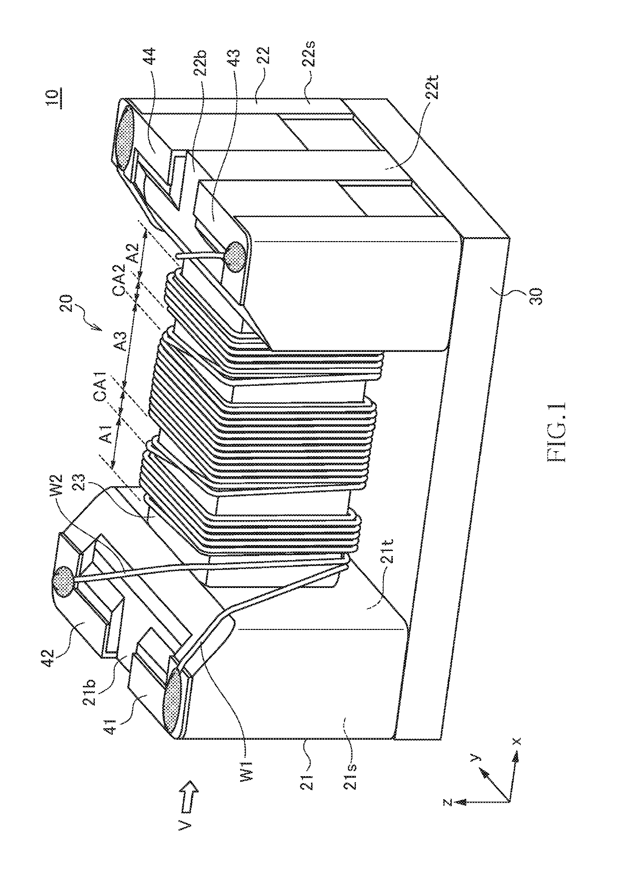
[0029]FIG. 1 is a schematic perspective view illustrating the outer appearance of a common mode filter 10 according to a preferred embodiment of the present invention.

[0030]As illustrated in FIG. 1, the common mode filter 10 according to the present embodiment includes a drum core 20, a plate core 30, first to fourth terminal electrodes 41 to 44, and first and second wires W1 and W2. The drum core 20 and plate core 30 are each made of a magnetic material having comparatively high permeability, such as an Ni—Zn based ferrite. The first to fourth terminal electrodes 41 to 44 are each a metal fitting made of a good conductor material such as copper. The first to fourth terminal electrodes 41 to 44 may be obtained by directly baking silver paste or the like onto the drum core 20.

[0031]The drum core 20 has a first flange part 21, a second flange part 22, and ...


PUM

PropertyMeasurementUnit
areaaaaaaaaaaa
frequencyaaaaaaaaaa
high-frequency characteristicsaaaaaaaaaa

Abstract

Disclosed herein is a common mode filter that includes a winding core part and first and second wires wound in a same direction around the winding core part. The first and second wires constitute a first winding block on one endmost side in an axial direction of the winding core part, a second winding block on other endmost side in the axial direction of the winding core part, and a third winding block positioned between the first and second winding blocks. The second winding block is a winding block at an odd-numbered position counted from the first winding block. The first and second wires cross each other in an area between the first and third winding blocks and in an area between the second and third winding blocks.

Description

BACKGROUND OF THE INVENTIONField of the Invention[0001]The present invention relates to a common mode filter and, more particularly, to a common mode filter of a type in which a pair of wires cross each other on the way and a manufacturing method therefor.Description of Related Art[0002]A common mode filter is widely used in many electronic devices, such as mobile electronic devices and on-vehicle LANs, as an element for removing common mode noise superimposed on differential signal lines. In recent years, a common mode filter using a surface-mountable drum core supersedes a common mode filter using a toroidal core (see JP 2014-199904 A).[0003]In the common mode filter described in JP 2014-199904 A, a pair of wires are made to cross each other on the way to thereby enhance symmetry between differential signals in a high-frequency region.[0004]However, when the pair of wires are made to cross each other on the way, the positional relationship between the wires is inverted, so that it...

Claims


Application Information

Patent Timeline
Patent Type & Authority Applications(United States)
IPC IPC(8): H01F27/28H03H7/09H03H1/00H01F17/04H01F27/06
CPCH01F27/2823H03H7/09H03H1/00H01F17/04H01F27/06H03H2001/0035H03H2001/0092H01F2017/0093H01F27/306H01F17/045H01F27/006H03H7/427
Inventor ASAI, YUGOKOBAYASHI, TSUTOMUURABE, DAISUKESUZUKIITO, EMITOMONARI, TOSHIO
Owner TDK CORPARATION
Why Eureka
Try Eureka