Method and apparatus for mapping the terminations of large numbers of communications circuits

a technology of terminations and communications circuits, applied in the field of telephone and data wire pairs, can solve the problems of unreliable original documentation of telecommunications wiring, poor documentation of typical wiring closets for telecommunications wiring, and inability to provide information regarding the location of the far ends of the terminated wire pairs

Inactive Publication Date: 2005-04-12
STEPHENS CHARLES DAVID
View PDF2 Cites 2 Cited by
  • Summary
  • Abstract
  • Description
  • Claims
  • Application Information

AI Technical Summary

Benefits of technology

The device and process described in this embodiment applies multiple recorded voice signals to an array of wire pairs in a bulk connector by attaching directly to the connector and thus all wire terminals simultaneously. The device further identifies the bulk termination block by one unique identification for the block and another unique identification on each connected wire pair. This allows for many such devices to operate at the same time in multiple locations to effect a complete facility wire mapping in one step. The device uses a ones density encoding for the voice signal such that no power consuming active analog electronics nor extensive data busses are required to recreate the multiple voice signals. Configuration switches are provided to allow each unit to have a unique unit identification to identify the block it is attached to.

Problems solved by technology

As a result of the rapid changes in telecommunications technology and business climate, the typical wiring closet for telecommunications wiring is poorly documented.
As office occupants move and telecommunications equipment is upgraded, any original documentation for telecommunications wiring is usually unreliable.
These termination connectors provide some order to the telecommunications wiring but do not provide any information regarding the location of the far ends of the terminated wire pairs.
The difficulty in determining the routing of office wiring has resulted in a situation where large changes in the wire routing is not accomplished by simply moving interconnect jumpers but by abandoning existing telecommunications wiring and installing new wiring.
This practice has resulted in large amounts of unused telecommunications wiring in buildings thus effecting fire safety.
This process limits the speed in which large numbers of pairs can be mapped because only one craft person may originate a tracing signal at a time.
The drawback to this device is that it only has one voice circuit and thus can only signal one pair at a time.
Without being able to identify every connection, the signal source moves result in lost craft time and repeated testing of unknown terminals in individual offices.

Method used


Image

  • Method and apparatus for mapping the terminations of large numbers of communications circuits
  • Method and apparatus for mapping the terminations of large numbers of communications circuits
  • Method and apparatus for mapping the terminations of large numbers of communications circuits

Examples


Embodiment Construction

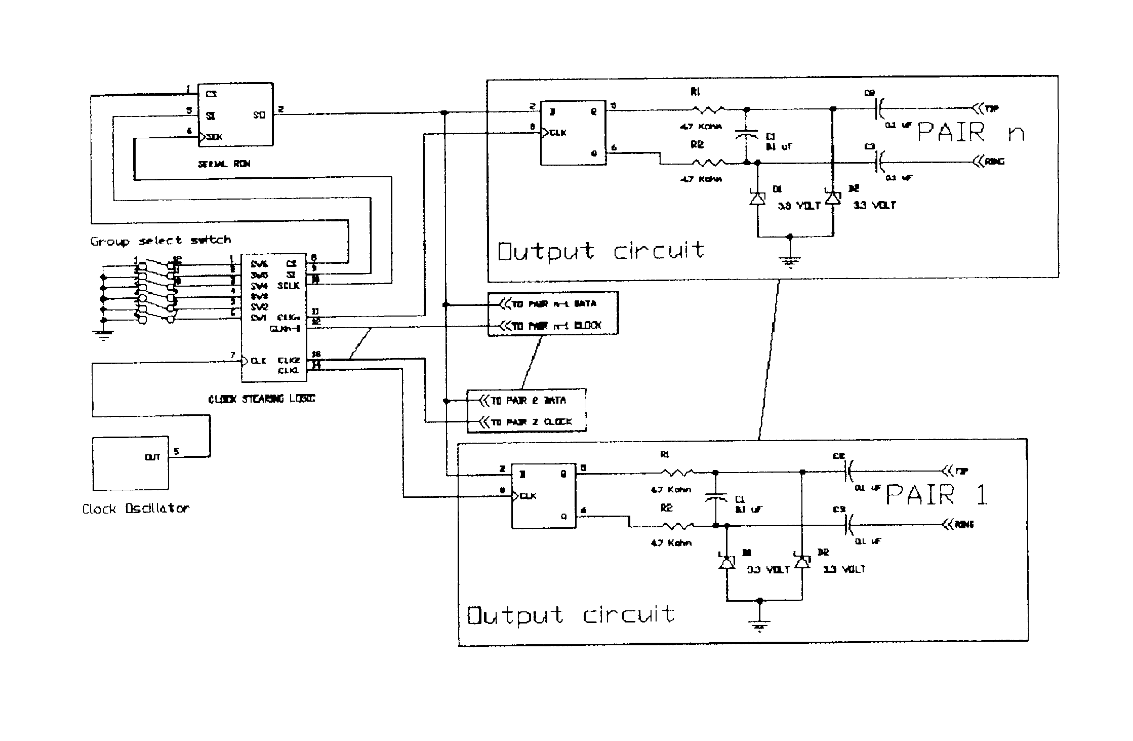
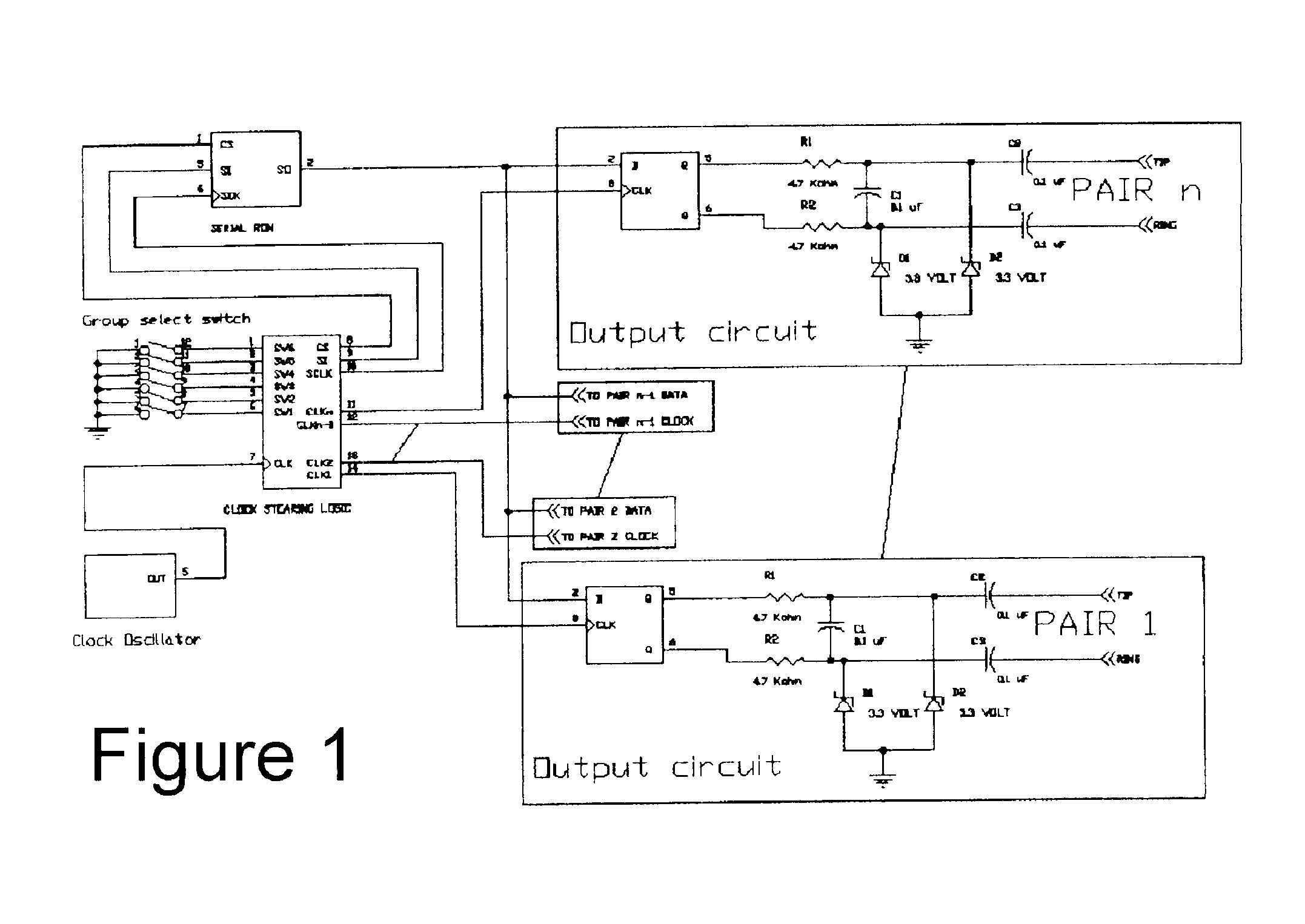
A device and process to enable workers to identify individuals and their associated groups of telecommunication wire pairs among large number of such wires at multiple locations simultaneously. The process involves placing a unique voice signal on each telecommunication wire pair that both identifies the individual as well as the grouping of the telecommunication wire pair.

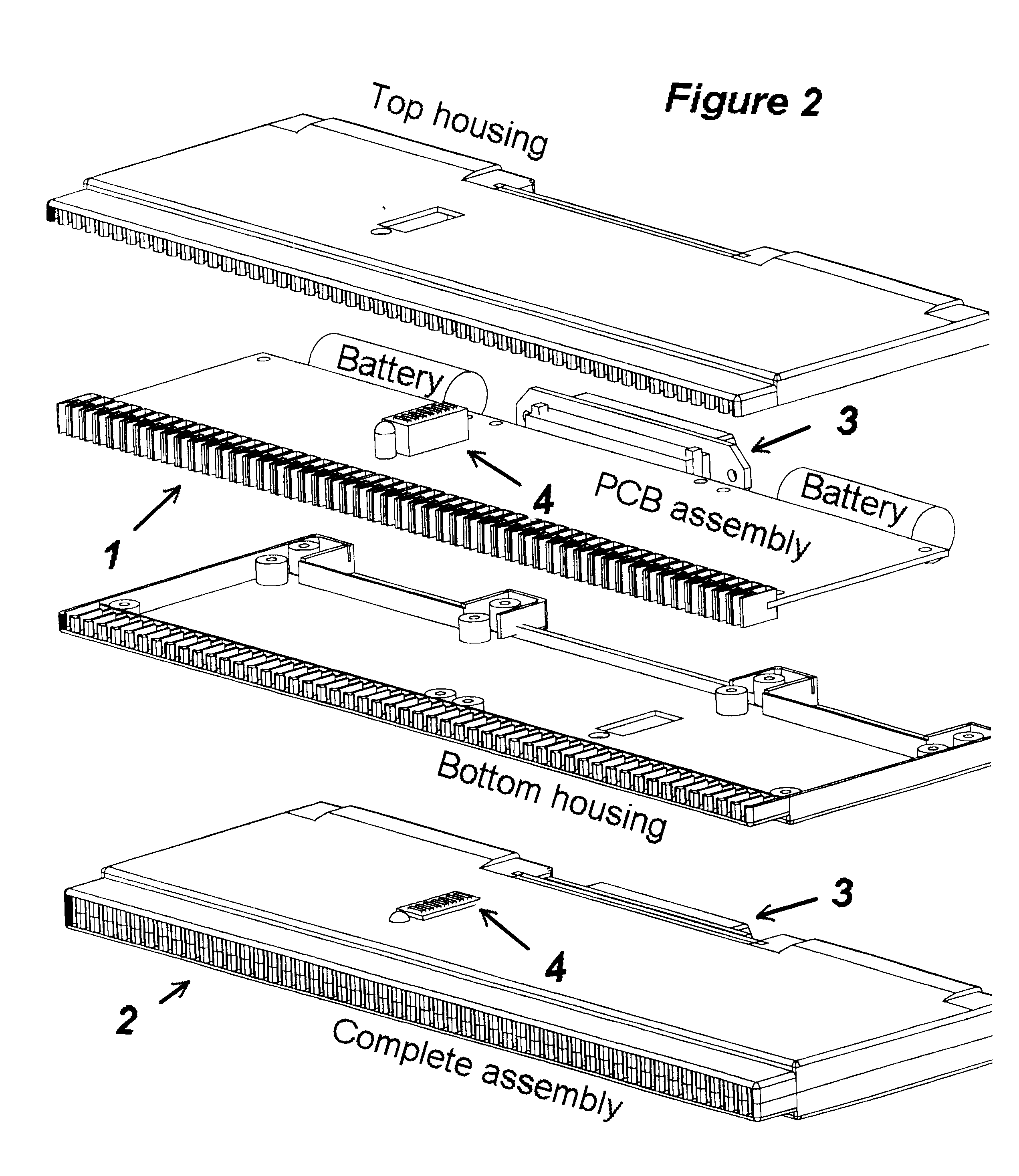
The voice signal consists of two phases. The first phase is a unique group identification shared by all member circuits of a group and the second phase is an individual identification unique to each member of a group. The device to generate the voice signals is contained within a bulk connector (FIG. 2—2) such that each circuit path to be identified within the connected cable does not need to be connected individually. This is accomplished through connector clips along one edge of the unit (FIG. 2-1) that make electrical contact directly to the terminals in the connector block. An alternative bulk connection (FIG....


PUM


Abstract

An apparatus and method for the efficient mapping of connectivity of telecommunications circuits where large numbers of such circuits are terminated at one end in concentrated bulk terminations. The apparatus regenerates multiple speech signals in a bulk termination adapter identifying both the bulk connector and the individual circuits terminating in the connector. A selectable group identity code allows many such units to be employed simultaneously to effect efficient mapping of hundreds of telecommunications circuits in one step even if concentration points occur in disparate locations. Speech reproduction is accomplished through a serial bit stream where the ratio of one bits to zero bits, varying with time, re-establishes a voice frequency signal with the aid of a simple filter circuit.

Description

BACKGROUND OF INVENTIONThis invention relates to the process of discovering the routing of a plurality of signal wires and more particularly telephone and data wire pairs, in a building environment.As a result of the rapid changes in telecommunications technology and business climate, the typical wiring closet for telecommunications wiring is poorly documented. As office occupants move and telecommunications equipment is upgraded, any original documentation for telecommunications wiring is usually unreliable. In order to handle the large number of wire pairs typically found in an office environment, bulk termination connectors were created and standardized. These termination connectors provide some order to the telecommunications wiring but do not provide any information regarding the location of the far ends of the terminated wire pairs.The difficulty in determining the routing of office wiring has resulted in a situation where large changes in the wire routing is not accomplished ...

Claims


Application Information

Patent Timeline
Patent Type & Authority Patents(United States)
IPC IPC(8): H04M1/24H04M11/00H04M1/00H04M3/22H04Q1/14
CPCH04M3/22H04Q1/149H04M3/229
Inventor STEPHENS, CHARLES DAVID
Owner STEPHENS CHARLES DAVID
Why Eureka
Try Eureka