CNC glass cutting line with dynamic continuous production control system

a production control and control system technology, applied in the direction of instruments, furniture, charge manipulation, etc., can solve the problems of harp racks generally not being moved until the end of the day, each system is limited by the number, and the existing system is limited

Inactive Publication Date: 2005-04-12
BILLCO MFG
View PDF5 Cites 13 Cited by
  • Summary
  • Abstract
  • Description
  • Claims
  • Application Information

AI Technical Summary

Problems solved by technology

The existing systems are limited by several problems.
First, each system is limited by the number of available slots in the available harp racks.
Second, the harp racks generally cannot be moved until the entire production run is completed, including the recuts at the end of the batch process.
Third, the existing last sheet problem increases yield loss, even with recuts incorporated into the last sheet.
Additionally, the existing system does not easily accommodate special pieces not accounted for in the production run.

Method used


Image

  • CNC glass cutting line with dynamic continuous production control system
  • CNC glass cutting line with dynamic continuous production control system
  • CNC glass cutting line with dynamic continuous production control system

Examples


Embodiment Construction

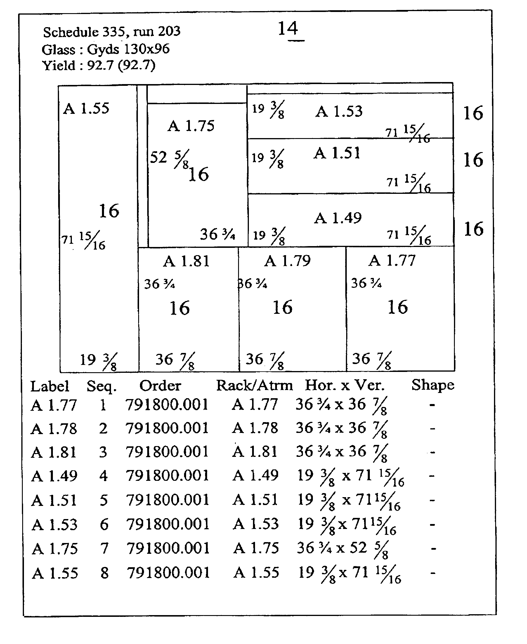
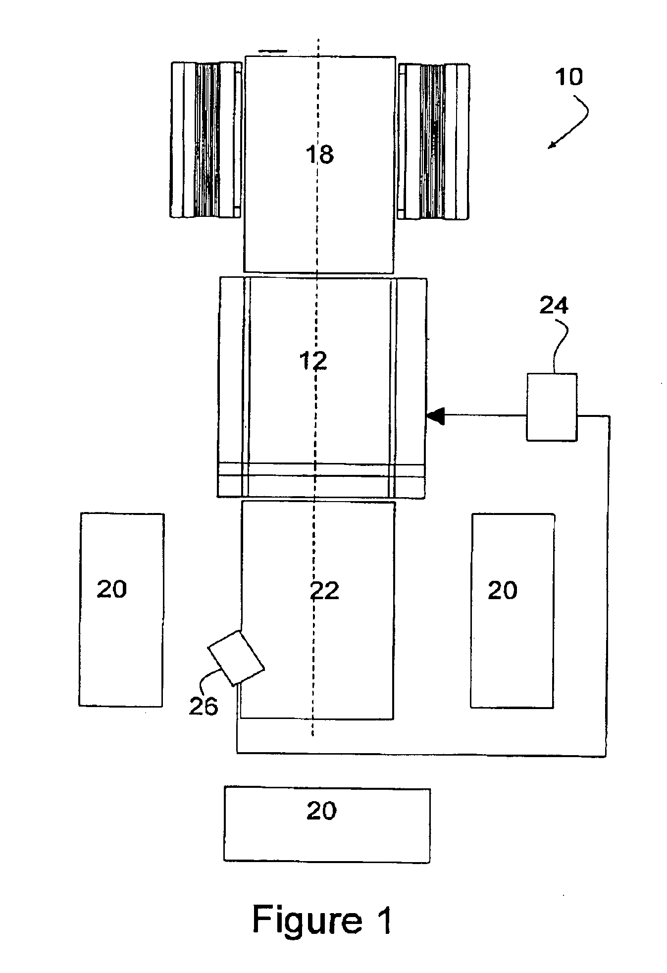
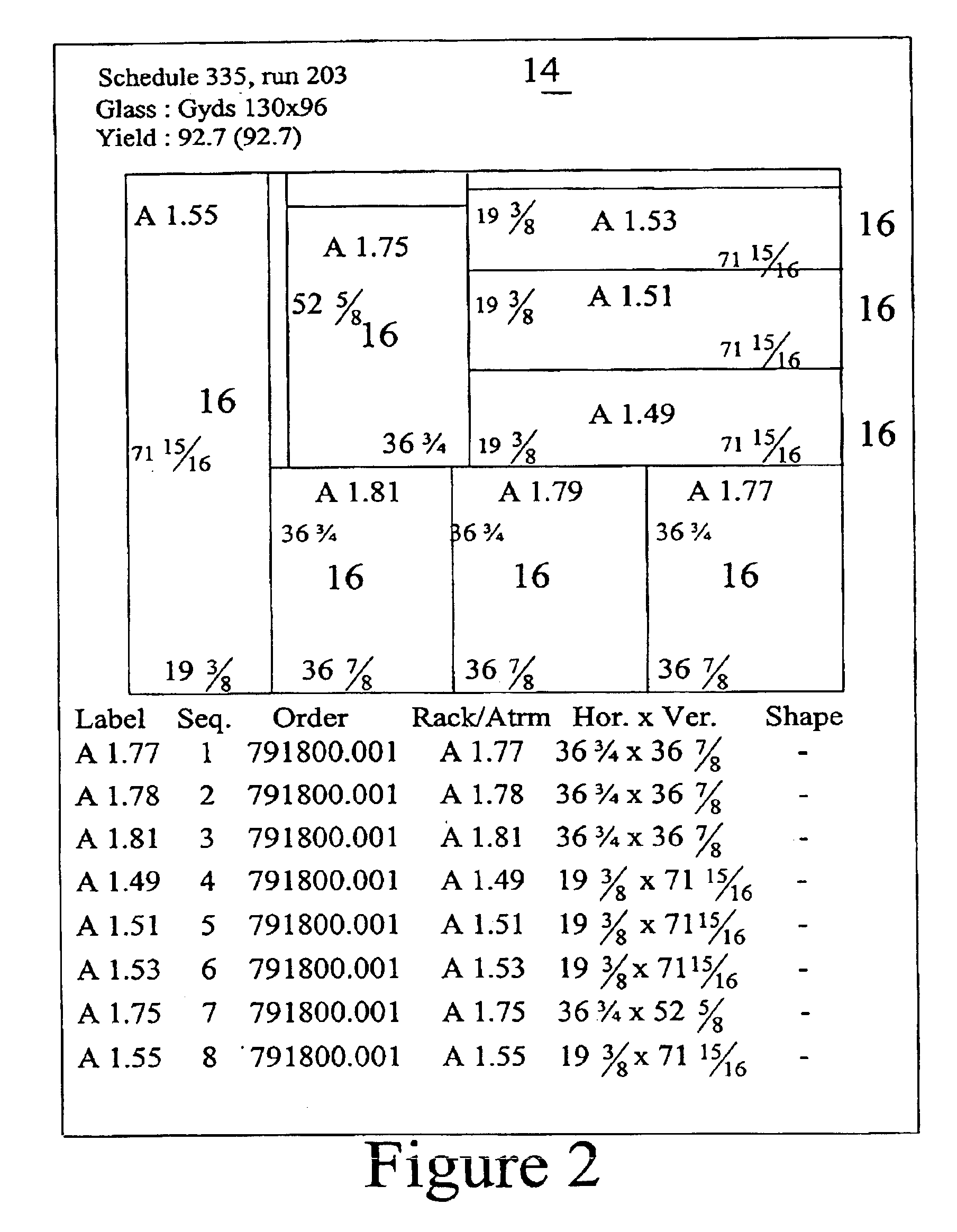
FIG. 1 schematically illustrates a glass product cutting line 10 according to the present invention. The central component of the cutting line 10 is a computer controlled of CNC glass cutting table 12 for cutting sheets of glass 14 into cut glass workpieces 16. The cutting table 12 is well known in the art such as those sold by Billco Manufacturing, Inc. The table 12 generally includes a cutting or scoring head mounted on a carriage which, in turn, is mounted on a bridge over the table surface. The carriage and bridge from an X-Y positioning system for the cutting head.

A feeding device 18 is provided upstream of the table 12 for feeding glass sheets 14 to the glass cutting table 12. The feeding device 18 may include an air float table, such as manufactured by Billco Manufacturing Inc. Additionally, the feeding device 18 may include an alignment mechanism for properly positioning the glass sheets 14 on the table 12. The feeding device 18 may include manual input for loading and posit...


PUM

PropertyMeasurementUnit
timeaaaaaaaaaa
weightsaaaaaaaaaa

Abstract

A glass product cutting line includes a CNC cutting table, a sheet feeding device for feeding glass sheets to the glass cutting table, a plurality of harp racks, a sorting device and a dynamic cutting line control system. The control system optimizes the workpiece layout on the individual sheets with a biasing favoring individual workpieces assigned to a leading harp rack. The bias tends to cut workpieces of the leading harp rack on leading sheets fill the leading harp rack in a minimum time. The system allows for removal of a filled leading harp rack, by designating a new leading harp rack for the control system, which then dynamically adjusts the bias and associated cutting scheduling.

Description

BACKGROUND OF THE INVENTION1. Field of the InventionThe present invention relates to CNC controlled machines with continuous production control. Specifically, the invention relates to a CNC controlled glass cutting line including a glass table with a dynamic, continuous production control system.2. Background InformationGlass cutting lines, including glass cutting tables, are well-known in the art, such as those sold by the assignee of the present invention, Billco Manufacturing, Inc. The central piece of equipment in the glass cutting line is the glass cutting table, examples of which are described in U.S. Pat. Nos. 5,791,971 and 6,463,762 and pending patent application Ser. No. 09 / 277,534, which are incorporated herein by reference. The glass cutting table is designed to cut generally rectangular glass sheets into a plurality of individual glass workpieces for subsequent manufacturing. The typical glass cutting line will also include a sheet feeding device upstream of the glass cu...

Claims


Application Information

Patent Timeline
Patent Type & Authority Patents(United States)
IPC IPC(8): B65G49/06C03B33/00C03B33/023C03B33/037B65G49/05
CPCB65G49/068C03B33/037C03B33/023Y10T83/04Y10T83/155Y02P40/57
Inventor PASSANT, JOHANNES F.
Owner BILLCO MFG
Why Eureka
Try Eureka