
Tributary analysis monitoring system

a monitoring system and tributary analysis technology, applied in the direction of instruments, structural/machine measurement, vehicle testing, etc., can solve the problems of exacerbated above-described problems associated with current performance monitoring systems, a large amount of time and expense associated with such application specific designs, and limited value of such presentations

Inactive Publication Date: 2005-04-12
NAT AERONAUTICS & SPACE ADMINISTATION UNITED STATES OF AMERICA AS REPRESENTED BY THE ADMINISTATOR
View PDF13 Cites 20 Cited by
  • Summary
  • Abstract
  • Description
  • Claims
  • Application Information

AI Technical Summary

Benefits of technology

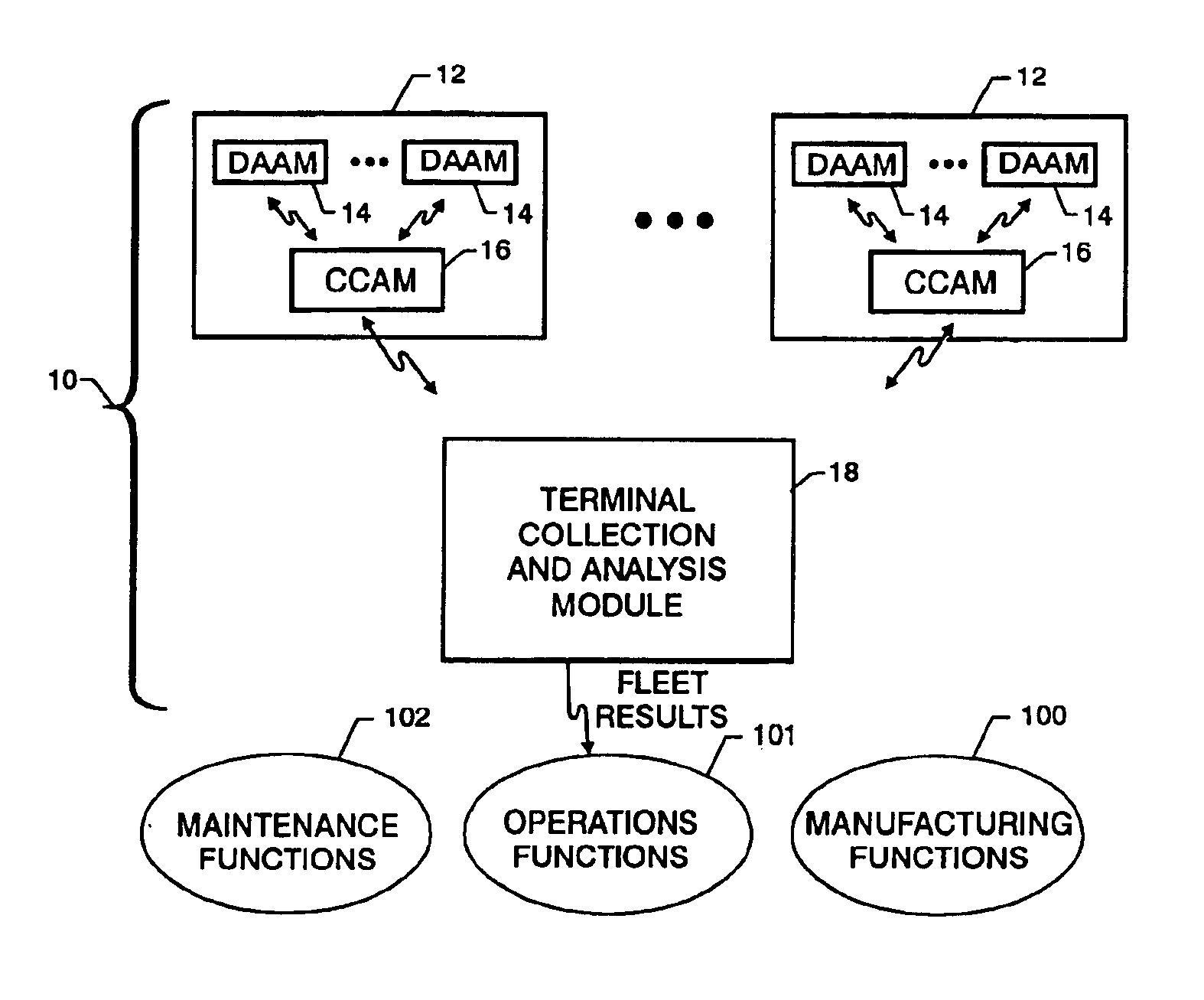
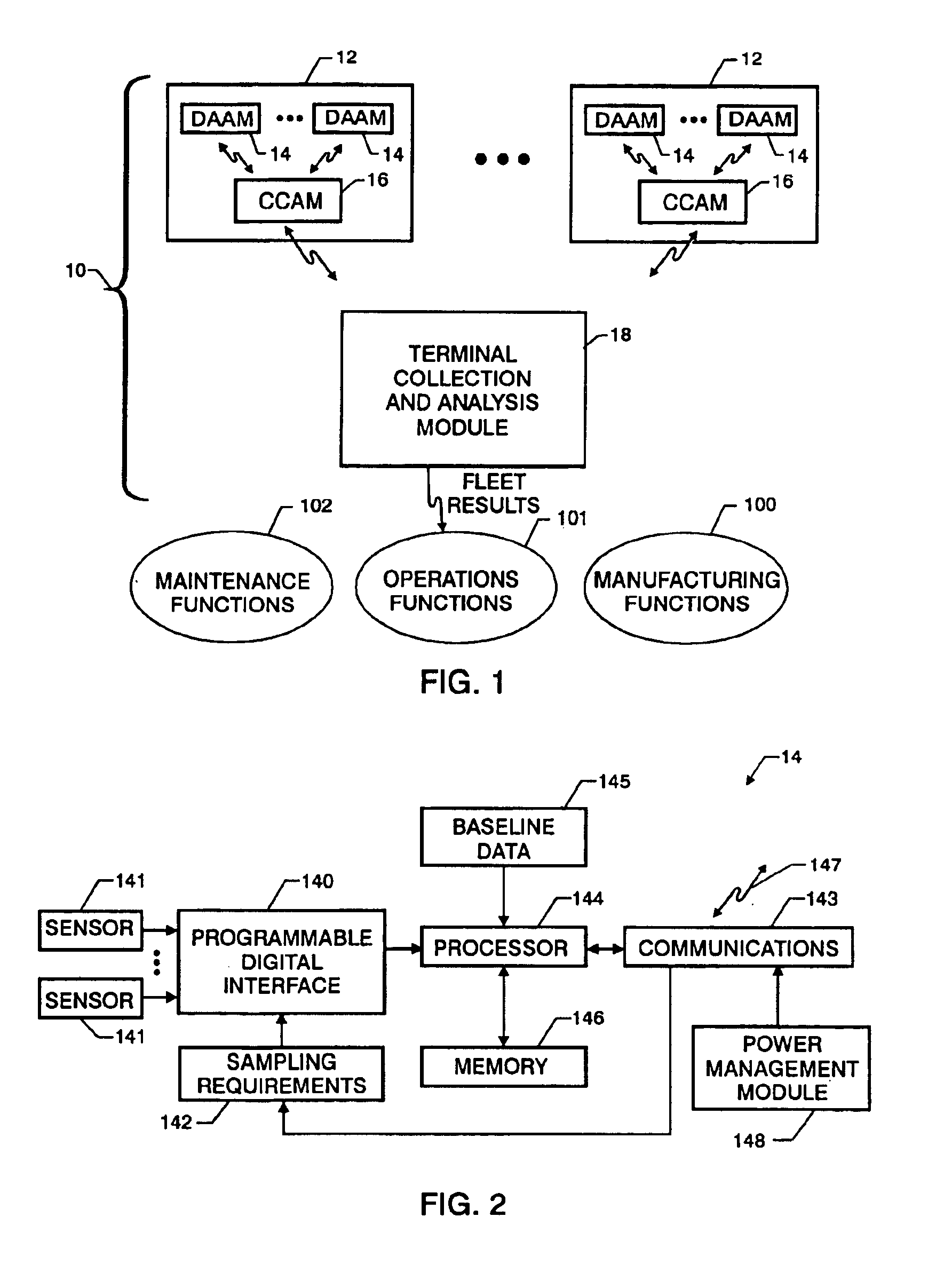
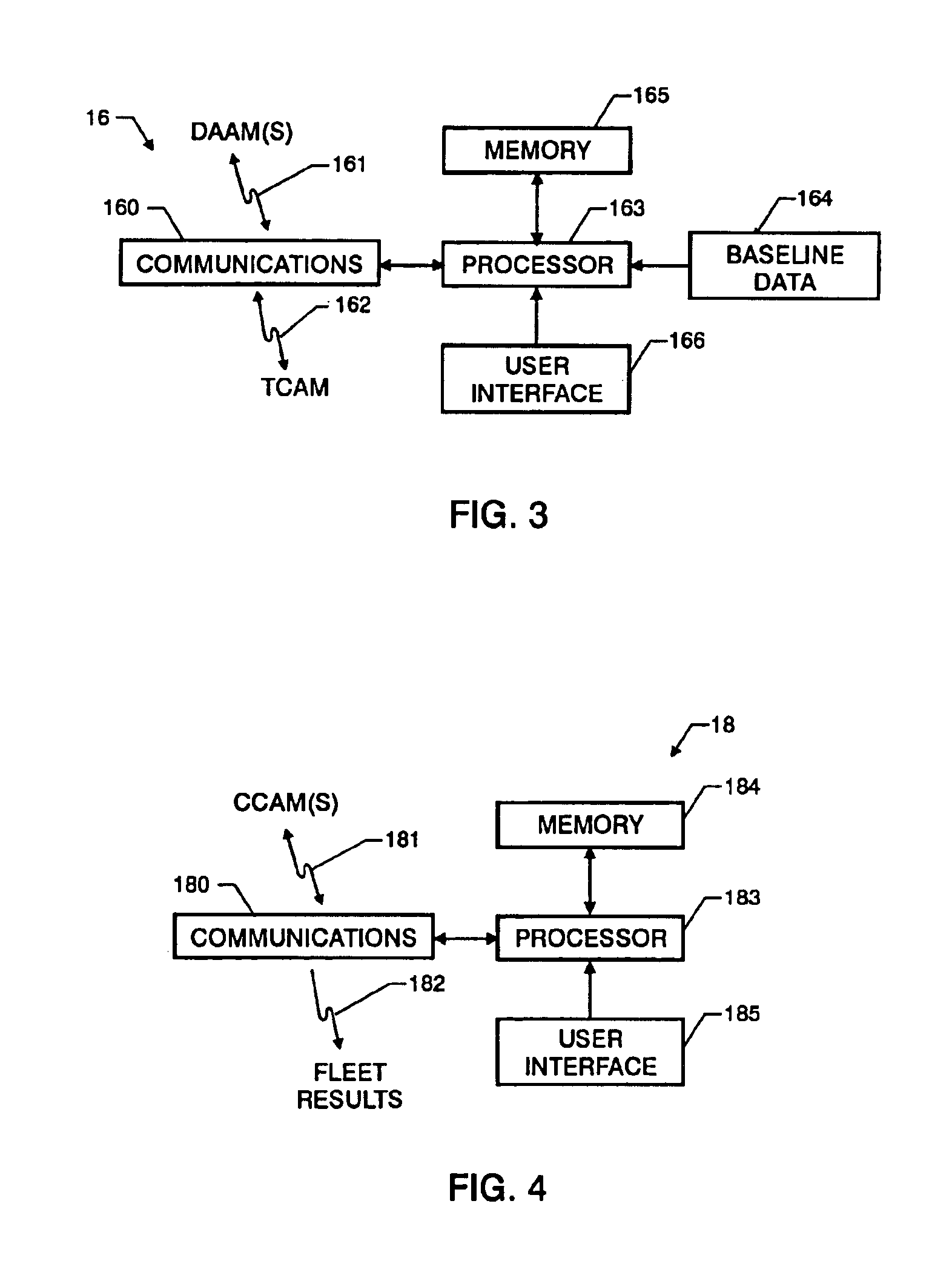
"The present invention provides an architecture for autonomously monitoring a group of identical or similar systems such as a fleet of vehicles. The monitoring system includes at least one data acquisition and analysis module (DAAM) mounted on each vehicle in the fleet. The DAAM collects data indicative of measurable attributes of the vehicle and analyzes the data to generate analysis results that identify the state of a plurality of systems of the vehicle based on the measurable attributes. The control module collects the analysis results from the DAAM and analyzes them to generate vehicle status results that identify potential sources of vehicle anomalies based on the state of the plurality of systems. The terminal module collects the analysis results and vehicle status results from the control module and analyzes them to generate fleet results that identify multiple occurrences of vehicle anomalies and multiple occurrences of those vehicle systems operating at a performance level that is unacceptable. The monitoring system can be adapted to work with a variety of systems to be monitored and can provide an indication of possible fleet-wide problems as well as individual vehicle problems. The technical effects of the invention include improved safety and efficiency of vehicle groups and early detection of potential problems."

Problems solved by technology

As a result, there is a great deal of time and expense associated with such application specific designs.
However, the value of such presentation is limited.
The above-described problems associated with current performance monitoring systems are further exacerbated when the performance of a number of similar systems is to be monitored.
However, using current technology, data from individual vehicles in the fleet would have to be collected and then analyzed for problematic trends.
Such analysis may be too little or too late to prevent a catastrophic system failure.

Method used


Image

  • Tributary analysis monitoring system
  • Tributary analysis monitoring system
  • Tributary analysis monitoring system

Examples


Embodiment Construction

Referring now to the drawings, and more particularly to FIG. 1, an embodiment of a tributary analysis monitoring system in accordance with the present invention is shown and referenced generally by numeral 10. By way of illustrative example, monitoring system 10 will be described for its use in monitoring a fleet of vehicles 12 (e.g., ground vehicles, aircraft, underwater vehicles, etc.) where each vehicle in the fleet is similar or nearly identical in design and construction, although vehicle parts and sub-systems may originate from different vendors. Although vehicle fleet monitoring is provided as an example, the invention is not limited thereto. It can also be applied to the monitoring of other systems such as manufacturing plants, structures, including buildings and bridges, and patients under medical care.

Monitoring system 10 will first be described in terms of a general overview with the aid of FIG. 1. There are three operational levels to monitoring system 10 with the first ...


PUM


Abstract

A monitoring system for a fleet of vehicles includes at least one data acquisition and analysis module (DAAM) mounted on each vehicle in the fleet, a control module on each vehicle in communication with each DAAM, and terminal module located remotely with respect to the vehicles in the fleet. Each DAAM collects / analyzes sensor data to generate analysis results that identify the state of a plurality of systems of the vehicle. Each vehicle's control module collects / analyzes the analysis results from each onboard DAAM to generate vehicle status results that identify potential sources of vehicle anomalies. The terminal module collects / analyzes the analysis results and vehicle status results transmitted from each control module from the fleet of vehicles to identify multiple occurrences of vehicle anomalies and multiple occurrences of those vehicle systems operating at a performance level that is unacceptable. Results of the terminal module's analysis are provided to organizations responsible for the operation, maintenance and manufacturing of the vehicles in the fleet as well as the plurality of systems used in the fleet.

Description

BACKGROUND OF THE INVENTION1. Field of the InventionThis invention relates to automated and autonomous monitoring systems. More specifically, the invention is an automated and autonomous monitoring system that i) performs data collection and analysis thereof at various data collection nodes onboard each vehicle in a fleet, ii) passes analysis results up to an onboard vehicle terminal and then on to a fleet-wide terminal for further analysis processing, and iii) notifies interested parties of problems with individual vehicles and fleet-wide problems (e.g., related to vehicle usage, maintenance, performance, damage or degradation) indicated by the analysis results.2. Description of the Related ArtMonitoring the performance of mechanical or structural systems is increasingly being accomplished with automated systems that collect performance data and present same to a user for analysis. The collected performance data can be related to system usage, maintenance, damage or degradation. Da...

Claims


Application Information

Patent Timeline
Patent Type & Authority Patents(United States)
IPC IPC(8): G07C5/00G07C5/08
CPCG07C5/085G07C5/008
Inventor WOODARD, STANLEY E.COFFEY, NEIL C.TAYLOR, BRYANT D.WOODMAN, KEITH L.
Owner NAT AERONAUTICS & SPACE ADMINISTATION UNITED STATES OF AMERICA AS REPRESENTED BY THE ADMINISTATOR
Learn More