Lockable firearm safety device

a firearm safety and locking technology, applied in the field of safety devices, can solve the problems that the type of locking device cannot be used with firearms of the type, and the loading or unloading of ammunition cannot be prevented, so as to prevent the operation of the firearm action and prevent the cycling or discharge of the firearm

Inactive Publication Date: 2005-04-19
STURM RUGER & CO INC
View PDF33 Cites 10 Cited by
  • Summary
  • Abstract
  • Description
  • Claims
  • Application Information

AI Technical Summary

Benefits of technology

[0010]In yet another embodiment, the clamp includes multiple tabs. When the clamp is positioned around the receiver, each tab is disposed within an opening in the firearm, thus preventing operation of the firearm action as well as insertion or removal of ammunition from the firearm.
[0011]In still another embodiment of the invention, the safety device is comprised of a base having a projecting tab and a flexible cable or strap selectively connectable to the base. When the base is positioned adjacent the receiver, the tab is disposed within an opened firearm action. The flexible cable or strap substantially encircles the firearm and connects to the base, securing the base to the firearm and preventing cycling or discharge of the firearm.

Problems solved by technology

The majority of such devices either interfere with the trigger or firing mechanism to prevent discharge of the firearm by an unauthorized user.
These devices generally are not directed to preventing loading or unloading of ammunition or disassembly of the firearm on which they are used.
Naturally, this type of locking device cannot be used with firearms of the type having only one aperture or with firearms of the type having an action that prevents threading the cable through the receiver from the first aperture to the second aperture.
Additionally, the known cable type locking devices are disadvantageous in that they do not prevent access to restricted areas of the firearm receiver.

Method used


Image

  • Lockable firearm safety device
  • Lockable firearm safety device
  • Lockable firearm safety device

Examples


Embodiment Construction

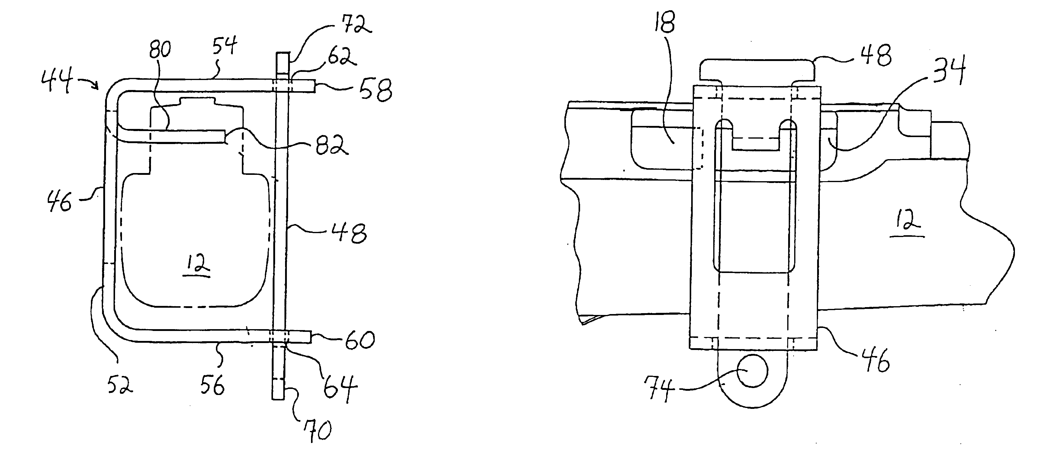
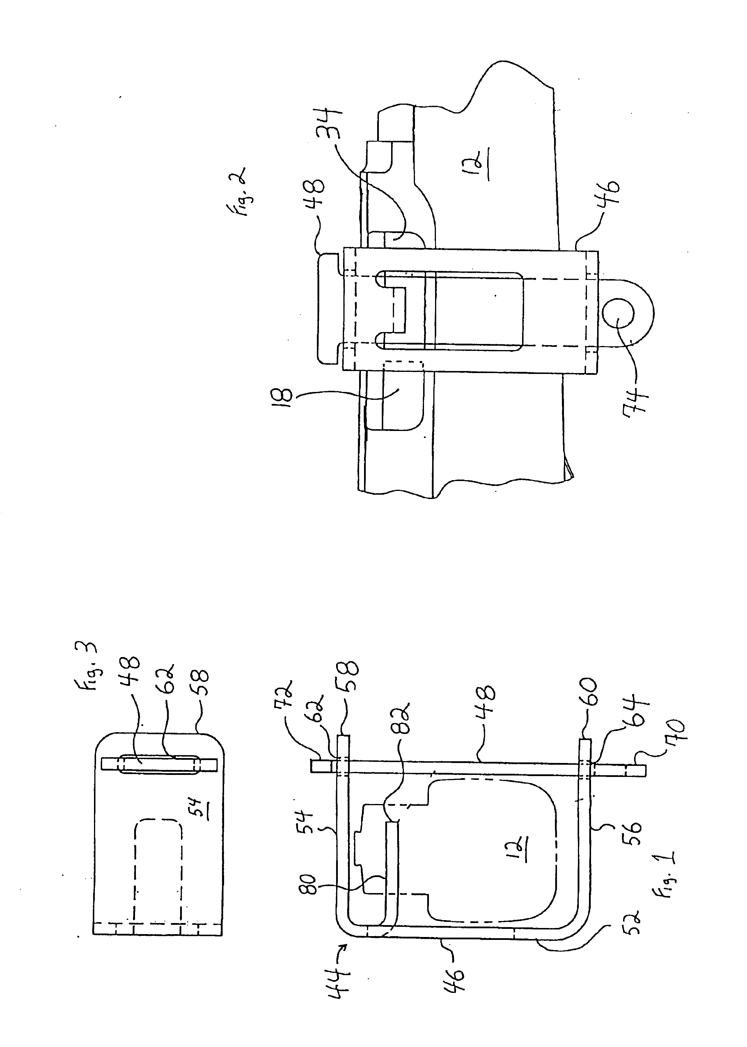
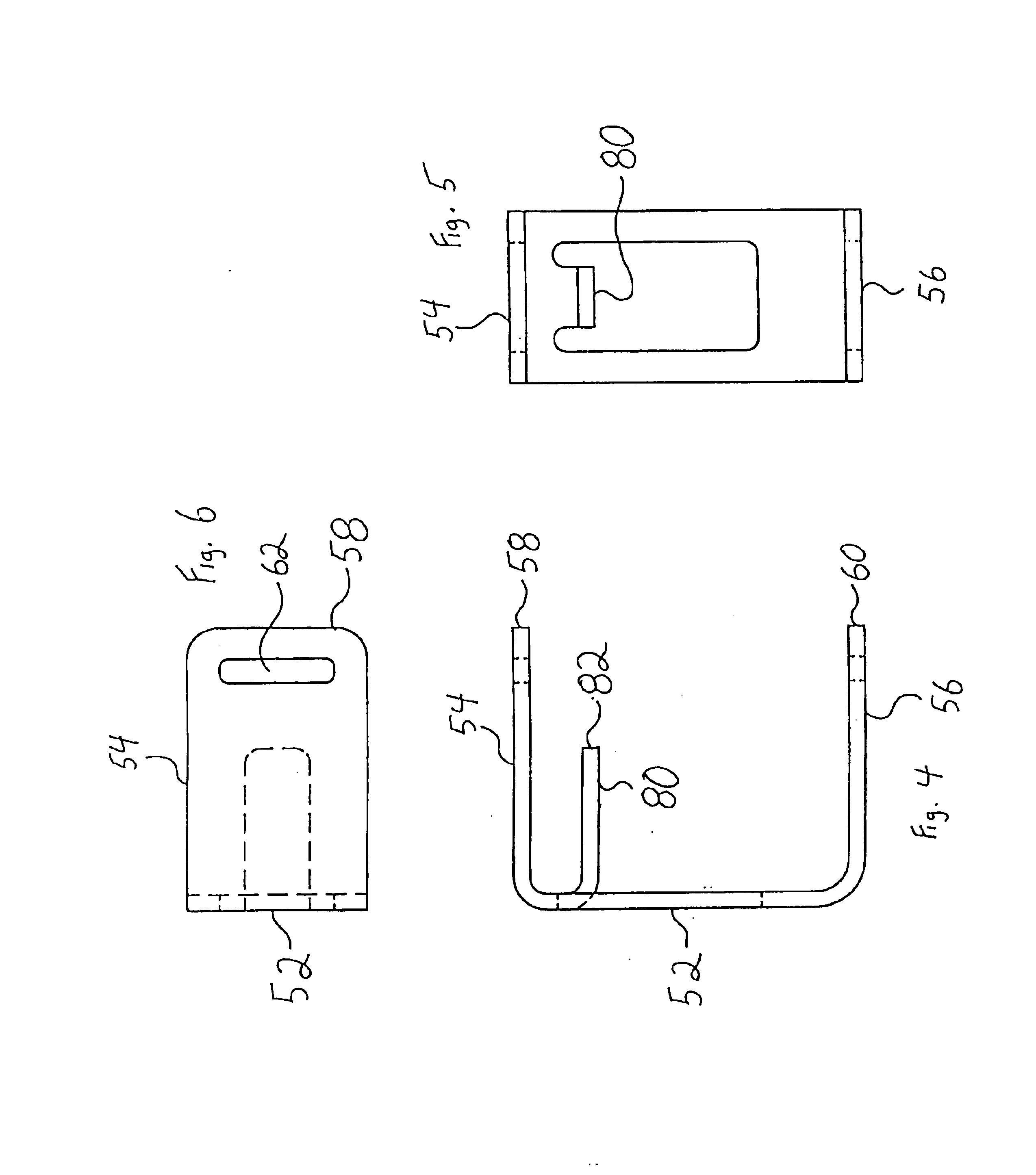
[0038]It should be understood that while the inventive firearm safety device is shown and described in some of the figures with relation to a rifle having a lever type action for clarity, the invention has application with all types of firearms, including rifles, shotguns and pistols, and all types of firearm actions, including automatic, semiautomatic, pump, bolt, single shot, superposed and side by side types. With reference to the drawings wherein like numerals represent like parts throughout the several figures, as shown best in FIG. 16, a firearm 10 typically comprises a receiver or frame 12 to which a barrel 14 is mounted. The receiver 12 includes an action or mechanism 16 that must be completely cycled for the firearm to be discharged. Typically, the action cycle comprises firing a loaded cartridge, extracting the fired cartridge from the chamber, ejection of the fired cartridge from the firearm, loading an unfired cartridge from an integral or separable magazine into the cha...


PUM


Abstract

A lockable safety device for use with a firearm. The device comprises a clamp or bracket that is engageable with a locking bar. When the clamp and locking bar are engaged with a firearm, access to, and use of, the firearm is restricted. The clamp can comprise a third arm projecting therefrom to prevent complete cycling of the firearm action.

Description

RELATED APPLICATIONS[0001]This application is a continuation of U.S. application Ser. No. 09 / 892,080, filed Jun. 26, 2001, now U.S. Pat. No. 6,694,659, the contents of which are incorporated herein by reference in their entirety.BACKGROUND OF THE INVENTION[0002]This invention relates generally to safety devices that are separate from, but securable to, a firearm to prevent discharge of the firearm by unauthorized users.[0003]The use of separable locks and other locking mechanisms, including electronic devices, to prevent discharge of a firearm by unauthorized persons is commonplace and a wide variety of devices and techniques have been advanced. The majority of such devices either interfere with the trigger or firing mechanism to prevent discharge of the firearm by an unauthorized user. These devices generally are not directed to preventing loading or unloading of ammunition or disassembly of the firearm on which they are used.[0004]Cable type firearm locking devices are also known....

Claims


Application Information

Patent Timeline
Patent Type & Authority Patents(United States)
IPC IPC(8): F41A17/44F41A17/00
CPCF41A17/44
Inventor OLSEN, CHARLES A.
Owner STURM RUGER & CO INC
Why Eureka
Try Eureka