Device for introducing hot gas into a heating surface pipe of a waste heat boiler

a waste heat boiler and hot gas technology, applied in the mechanical details of gasifiers, furnaces, steam generation using hot heat carriers, etc., can solve the problems of unacceptably high surface temperature and/or unacceptably high mechanical and thermal loads, high thermal load, and high thermal load on the inlet area of the heat exchanger, etc., to achieve greater flow, enlarge the inlet geometry, and increase the mass flow rate

Inactive Publication Date: 2005-04-19
ARVOS GMBH
View PDF3 Cites 10 Cited by
  • Summary
  • Abstract
  • Description
  • Claims
  • Application Information

AI Technical Summary

Benefits of technology

[0019]The gas flow rate through an apparatus of the invention for the entry of hot gas into a heating surface tube of a waste heat boiler can exhibit significantly higher mass flow rates compared with an unsupported apparatus for the entry of hot gas into a heating surface tube of a waste heat boiler (the flow is greater by a factor of about 2 to 4), and in design terms there are addi

Problems solved by technology

The heat exchanger inlet areas that are exposed to the hot gas, in particular, are subjected to very high thermal loads.
Because of the high system pressure of the heat-absorbing medium (such as boiling water), additional high mechanical loads result that, among other things, also must be removed by the inlet areas or the devices provided for the hot gas to enter the heating surface tubes.
In this prior-art apparatus, components are present-and this applies in particular to the reversing caps where the gas enters the apparatus—at which

Method used


Image

  • Device for introducing hot gas into a heating surface pipe of a waste heat boiler
  • Device for introducing hot gas into a heating surface pipe of a waste heat boiler
  • Device for introducing hot gas into a heating surface pipe of a waste heat boiler

Examples


Embodiment Construction

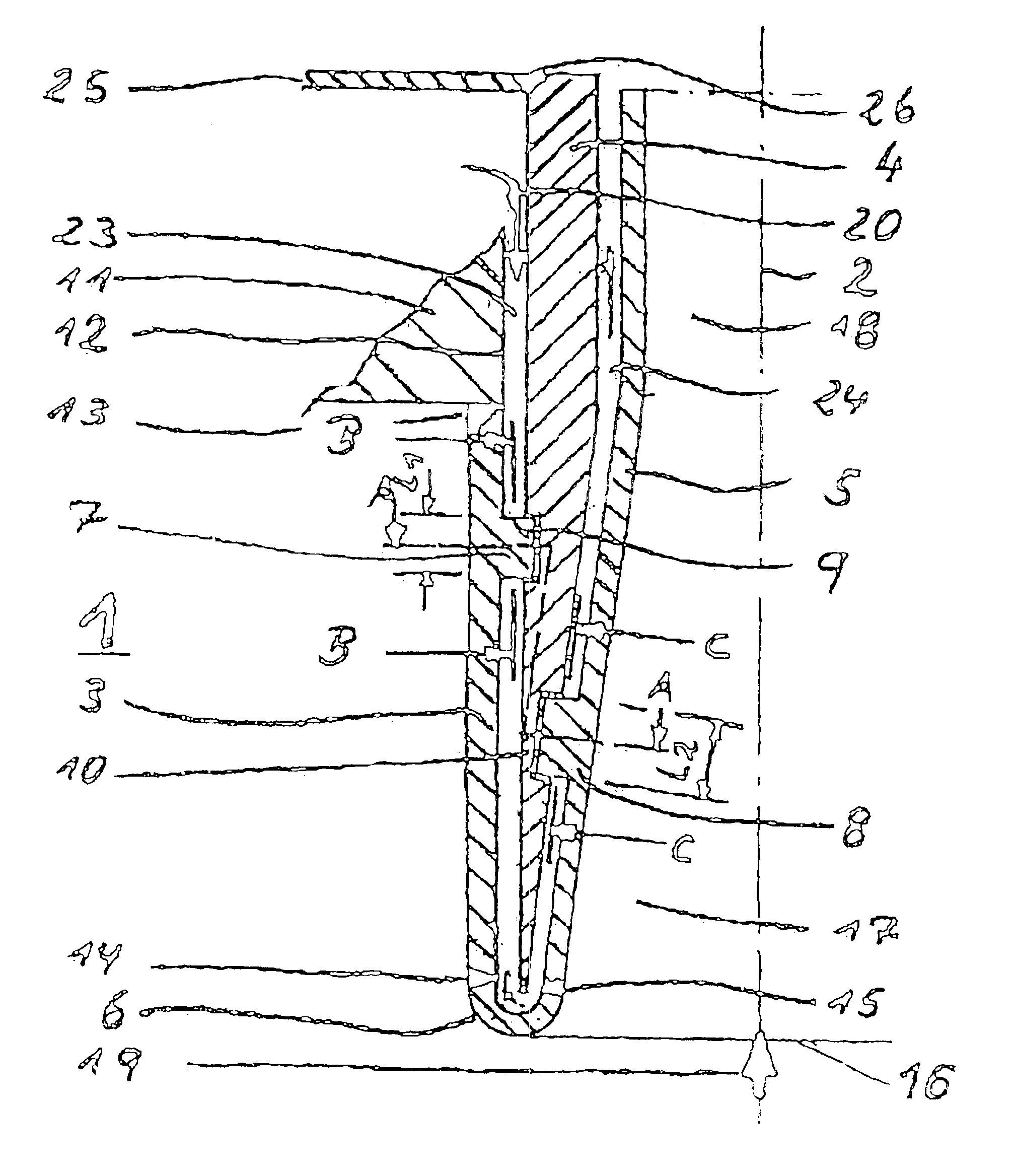
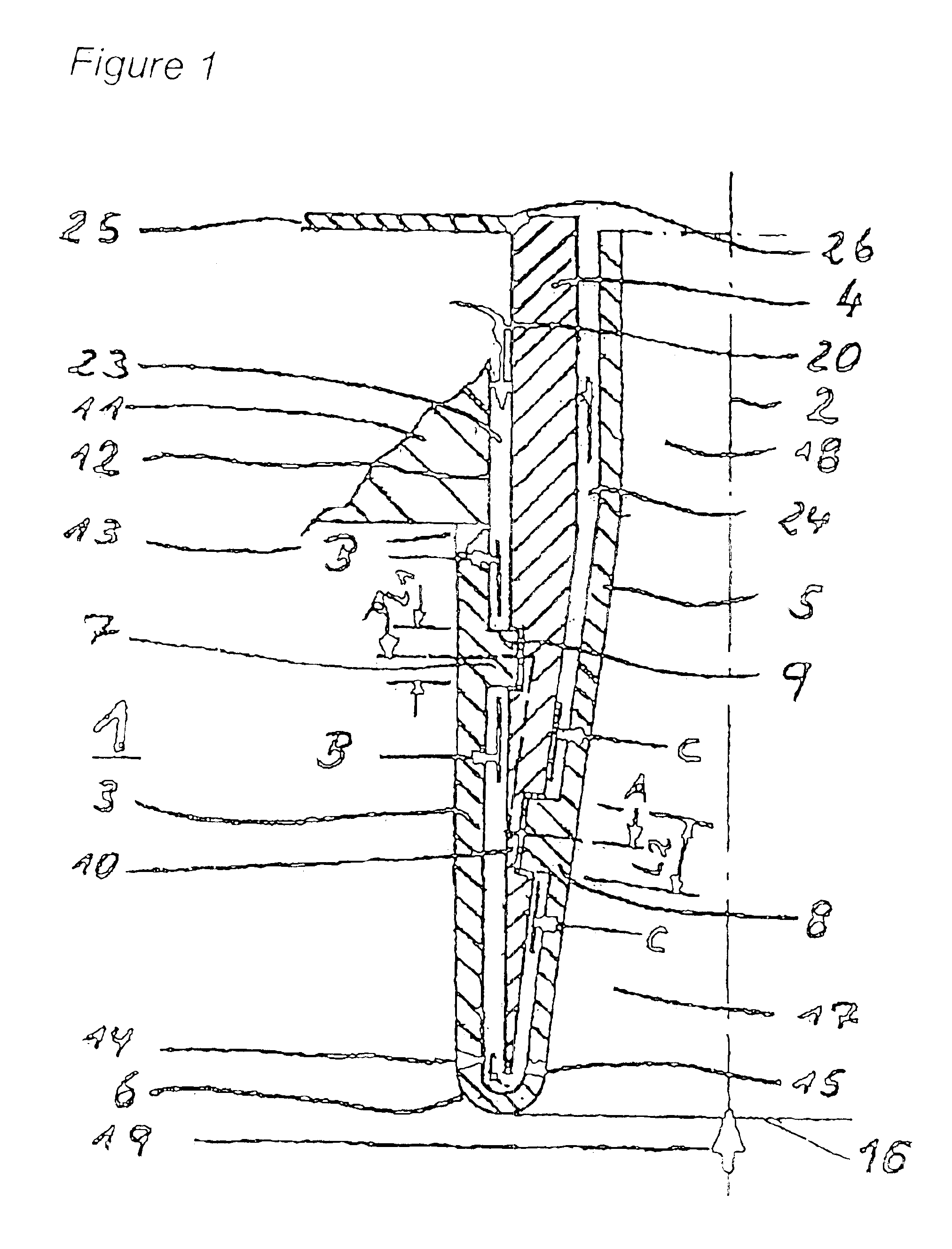
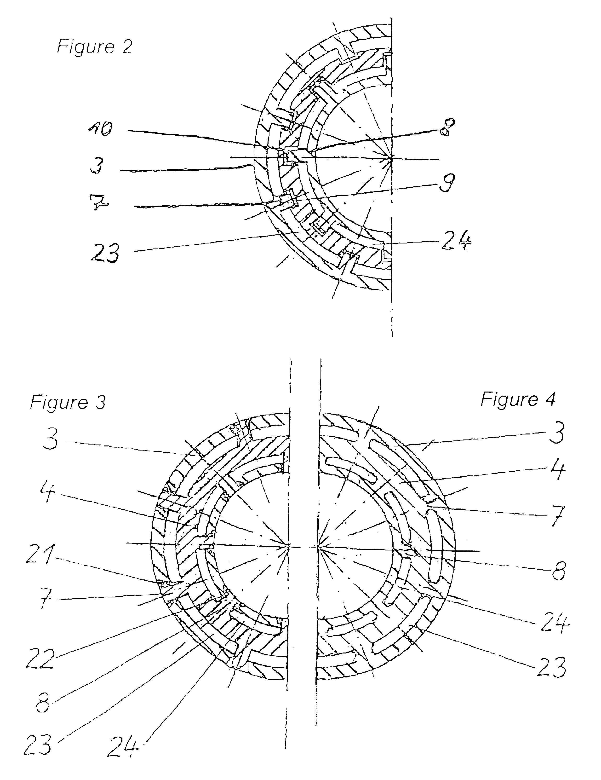
[0035]In FIG. 1 of the waste heat boiler that is represented here, only a part of the vessel wall, namely the tube base 11 is shown. This part is connected in the area of hole 12 to an apparatus 1 for the entry of the hot gas 19 into a heating surface tube of the waste heat boiler (not shown) by means of a weld 13. An outer tube 3 and inner or inlet tube 5 that is surrounded by the outer tube 3 are part of the apparatus 1 and are connected to each other by means of a rounded reversing cap 6. In the embodiment shown in FIG. 1, the reversing cap-which causes the coolant 20 to reverse the direction of flow within the apparatus 1, essentially by 180°, is configured as a part that is located in the reversing area of the apparatus 1 and that is connected to the outer tube 3 by means of a weld 14 and to the inner tube 5 by means of a weld 15. The reversing cap 6 defines a gas inlet port 16 from which gas enters the inner or inlet tube 5. The inner tube 5 has a conically narrowing section 1...


PUM


Abstract

A device for introducing hot gas into a heating surface pipe of a waste heat boiler includes an outer pipe that is connected to the boiler wall, preferably to the bottom of the pipe. The device also includes an inner pipe or entry pipe that has an admission section that is cylindrical or conically narrows and also has a discharge section that is connected to the heating surface pipe. The inner pipe is connected to the outer pipe via a rounded reversible cap while forming an entry opening for the hot gas. The inner pipe is surrounded by the outer pipe at a distance. The device also includes a coolant guiding pipe, which is placed between the outer pipe and the inner pipe and which extends into the proximity of the reversible cap. The guiding pipe is provided in the form of a force-transmitting component and is connected, in a removable or fixed manner, both to the inner pipe as well as to the outer pipe each time with at least three connecting ribs which are uniformly distributed over the periphery and which are provided for introducing or transferring forces.

Description

CROSS-REFERENCE TO RELATED APPLICATIONS[0001]This is the national stage of International Application No. PCT / DE02 / 02895, filed Aug. 7, 2002 and which designated the United States.BACKGROUND OF THE INVENTION[0002]The invention relates to an apparatus for the entry of hot gas into a heating surface tube of a waste heat boiler having an outer tube connected to the boiler wall, in particular to the tube base, and further having inner or inlet tube that is connected to the outer tube by means of a rounded reversing cap to form an inlet port for the hot gas and that is surrounded by the outer tube at a given distance and that has a cylindrical or conically narrowing inflow section and an outflow section that is connected to the heating surface tube, and having a coolant transport tube that is disposed between the outer tube and the inner tube and that extends into the vicinity of the reversing cap.[0003]In waste heat boilers or heat exchangers, hot gases (such as synthesis gases from part...

Claims


Application Information

Patent Timeline
IPC IPC(8): C10J3/00C10J3/86F22B1/18F22B1/00F28F9/02F28F9/18F28F9/04F28F19/00F27D17/00F27D1/14F27D9/00F22B37/12
CPCC10J3/86F22B1/1846F22B1/1884F28F19/002F27D17/001F28F9/0229F28F9/182C10J2200/09C10J2300/1884C10J2300/1892F27D17/002F27D2009/0005F27D1/145Y02P20/129
Inventor GOTTSCHALK, HORSTSCHOTZ, MICHAEL
Owner ARVOS GMBH
Why Eureka
Try Eureka