
Over-pressure protection system

a protection system and overpressure technology, applied in the direction of valve operating means/releasing devices, service pipe systems, functional valve types, etc., can solve the problems of high-pressure source remaining connected to the low-pressure source, and the number of failures per unit of time is considerabl

Inactive Publication Date: 2005-04-19
SHELL OIL CO
View PDF7 Cites 95 Cited by
  • Summary
  • Abstract
  • Description
  • Claims
  • Application Information

AI Technical Summary

Benefits of technology

[0006]To this end, the over-pressure protection system according to the present invention comprises a conduit section extending between a pressure reduction valve and a low-pressure fluid handling system, a shut-off valve provided with an actuator arranged in the conduit section, pressure sensors arranged one on either side of the shut-off valve in the conduit section, a safety control system that communicates with the

Problems solved by technology

A disadvantage of the conventional over-pressure protection system is that the high-pressure source remains connected to the low-pressure handling system in case the shut-off valve fails and the mechanical relief valve opens.
Moreover, Applicant had studied the reliability of such a relief valve, and found that the number of failures per unit of time was considerable, more than 5 failures in 1000 years of service life.

Method used


Image

  • Over-pressure protection system
  • Over-pressure protection system

Examples


Embodiment Construction

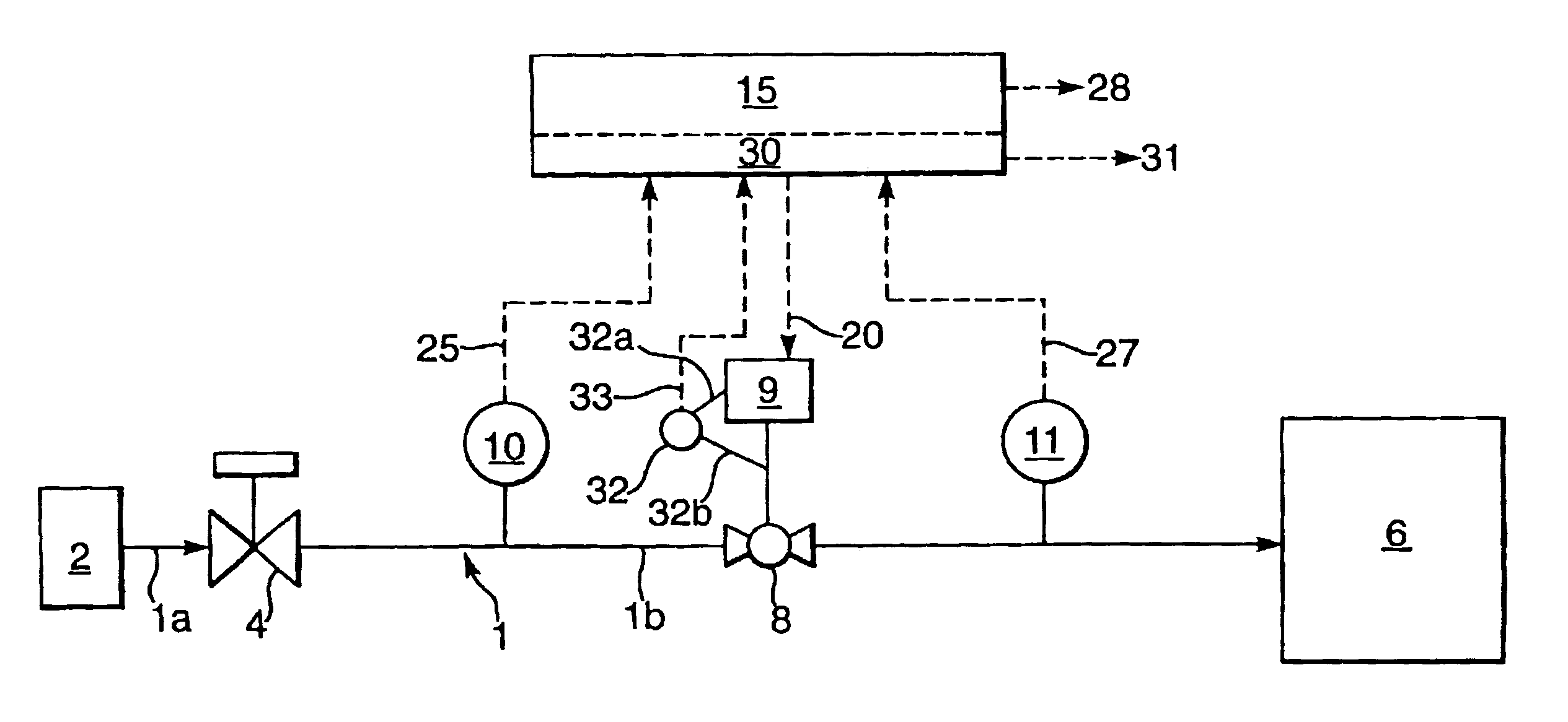
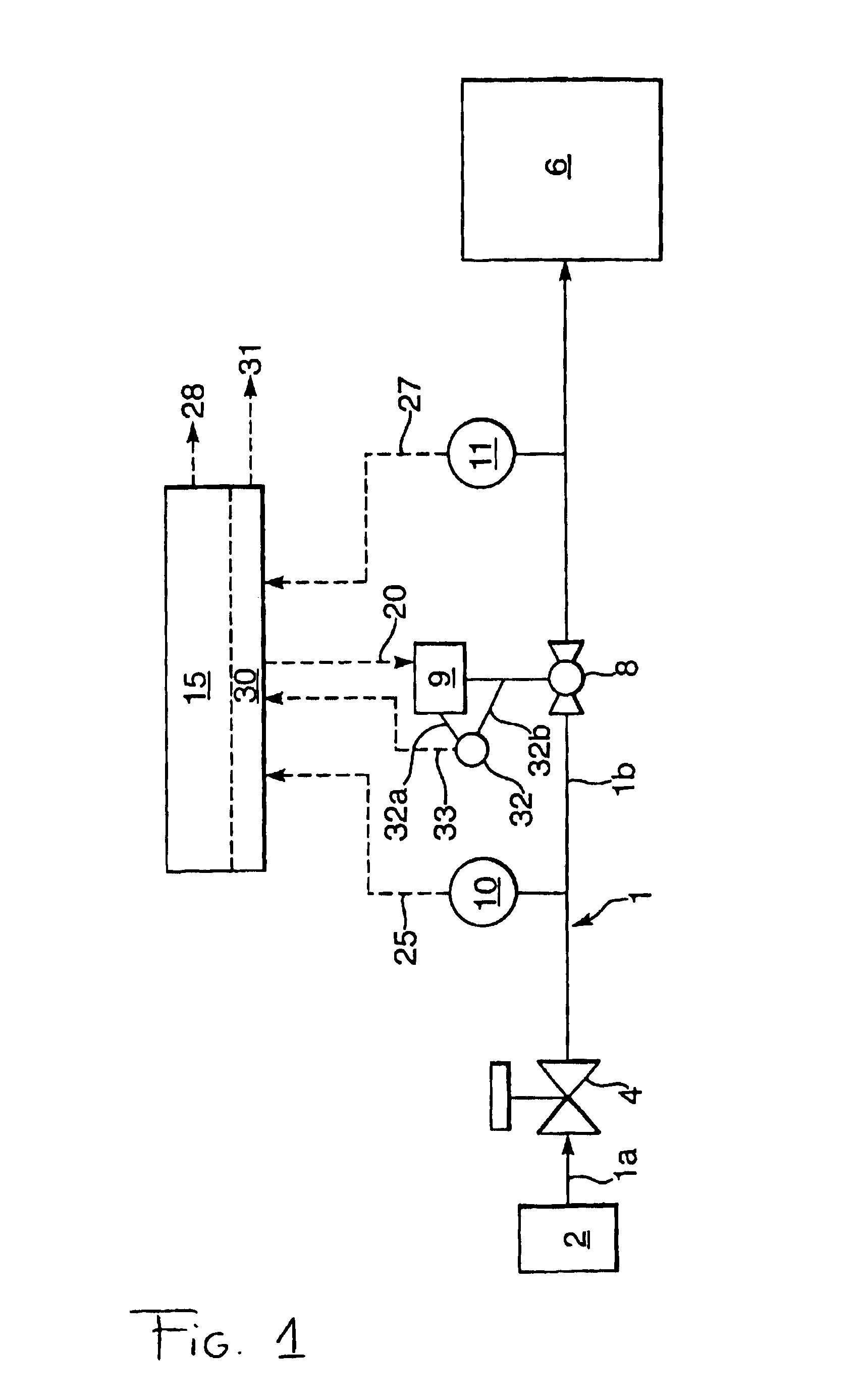
[0008]The invention will now be described in more detail with reference to the accompanying drawing, which shows schematically a conduit 1, which conduit 1 comprises a first conduit section 1a extending from a source 2 of high pressure to a pressure reduction valve 4, and a second conduit section 1b extending from the pressure reduction valve 4 to a low-pressure fluid handling system 6.

[0009]In the second conduit section 1b is arranged a shut-off valve 8 provided with an actuator 9. The shut-off valve 8 is for example a ball valve. In addition pressure sensors 10 and 11 are arranged on either side of the shut-off valve 8 in the conduit section 1b.

[0010]The over-pressure protection system further comprises a safety control system 15 that instructs the actuator 9 via conduit 20. The safety control system 15 further communicates with the sensors 10 and 11 via conduits 25 and 27 transmitting sensor signals to the safety control system 15. Suitably, the conduits 20, 25 and 27 are condui...


PUM


Abstract

An over-pressure protection system having a conduit section extending between a pressure reduction valve and a low-pressure fluid handling system, a shut-off valve provided with an actuator arranged in the conduit section, pressure sensors arranged one on either side of the shut-off valve in the conduit section, a safety control system that communicates with the actuator and the pressure sensors which produces a signal when it detects a high pressure in the conduit section, and a self-diagnostic system for checking the shut-off valve and the pressure sensors that communicates with the actuator, the pressure sensors and the safety control system, which self-diagnostic system produces a signal when it detects a failure in either the shut-off valve or the pressure sensors or both.

Description

[0001]The present application claims priority on European Patent Application 01309291.1 filed on 01 Nov. 2001.FIELD OF THE INVENTION[0002]The invention relates to an over-pressure protection system. The over-pressure protection system protects a facility for handling fluid at a low pressure, such as a pipeline or a plant, from becoming exposed to an over-pressure. An over-pressure is a pressure that exceeds the pressure maximum allowable operating pressure of the facility for handling low-pressure fluids.[0003]The facility is connected to the source of high pressure by a conduit. To control the fluid pressure in the facility, a pressure reduction valve is arranged in the conduit. To protect the facility from over-pressures, the over-pressure protection system is provided in the conduit downstream of the pressure reduction valve.[0004]The over-pressure protection system protects the low-pressure facility from over-pressures caused by failure of the upstream pressure reduction system....

Claims


Application Information

Patent Timeline
IPC IPC(8): F16K17/04F16K37/00
CPCF16K37/00F16K17/04Y10T137/7728Y10T137/8326Y10T137/7761F16K37/0025F16K37/0041F16K37/0083F16K51/00
Inventor KLAVER, THEODORUS CORNELISPETTITT, MARK
Owner SHELL OIL CO
Learn More