Arrow case

a protective case and archery equipment technology, applied in the field of molded protective cases, can solve the problems of large and cumbersome archery equipment, equipment is also delicate relative to its size, and the transportation of archery equipment, such as bows and arrows, is historically a difficult undertaking, and achieves the effect of non-deformation

Inactive Publication Date: 2005-04-19
PLANO MOLDING CO LLC
View PDF18 Cites 13 Cited by
  • Summary
  • Abstract
  • Description
  • Claims
  • Application Information

AI Technical Summary

Benefits of technology

[0010]It is therefore a general object of the present invention to provide a protective case for the transportat...

Problems solved by technology

Transporting archery equipment, such as bows and arrows, has historically been a difficult undertaking.
By their very nature, archery equipment is large and cumbersome.
The equipment is also delicate relative to its size.
In particular, modern bows have very complex structure in order to provide the sophisticated functions now expected.
While a bow may be disassembled for transportation, it is considered a major disadvantage if this is necessary.
Accuracy and alignment is lost if these bows are disassembled.
Furthermore, the bows and arrows are also very delicate when subjected to forces different from those of ordinary operation.
Slight or unseen damage to bows can result in catastrophic failure of the equipment, which could even injure the user.
An off-axis impact can destroy a carbon fiber arrow shaft.
For many reasons, there are obvious disadvantages to the soft-sided cases.
First, and foremost, is the lack of protection afforded the equipment inside.
As a result, they have rather limited usefulness for serious archers, or those concerned about the condition of their equipment.
Without a stiff exterior panel, the level of protection afforded is only sufficient for the infrequent or occasional user.
These soft cases are not approved for use in airplane travel.
One disadvantage is the size of such a case.
Available only in conventional rectangular-shaped...

Method used


Image

  • Arrow case
  • Arrow case
  • Arrow case

Examples


Embodiment Construction

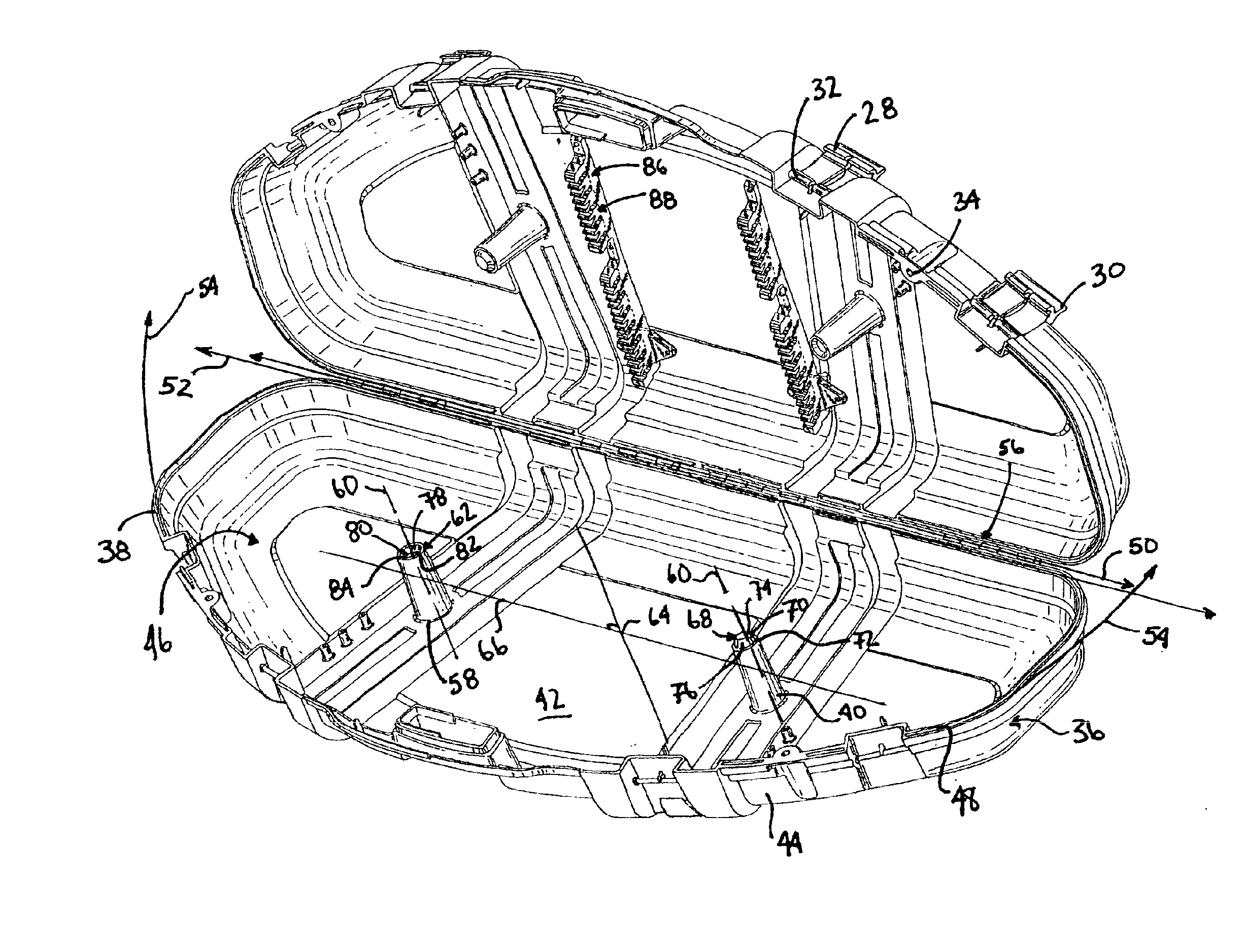
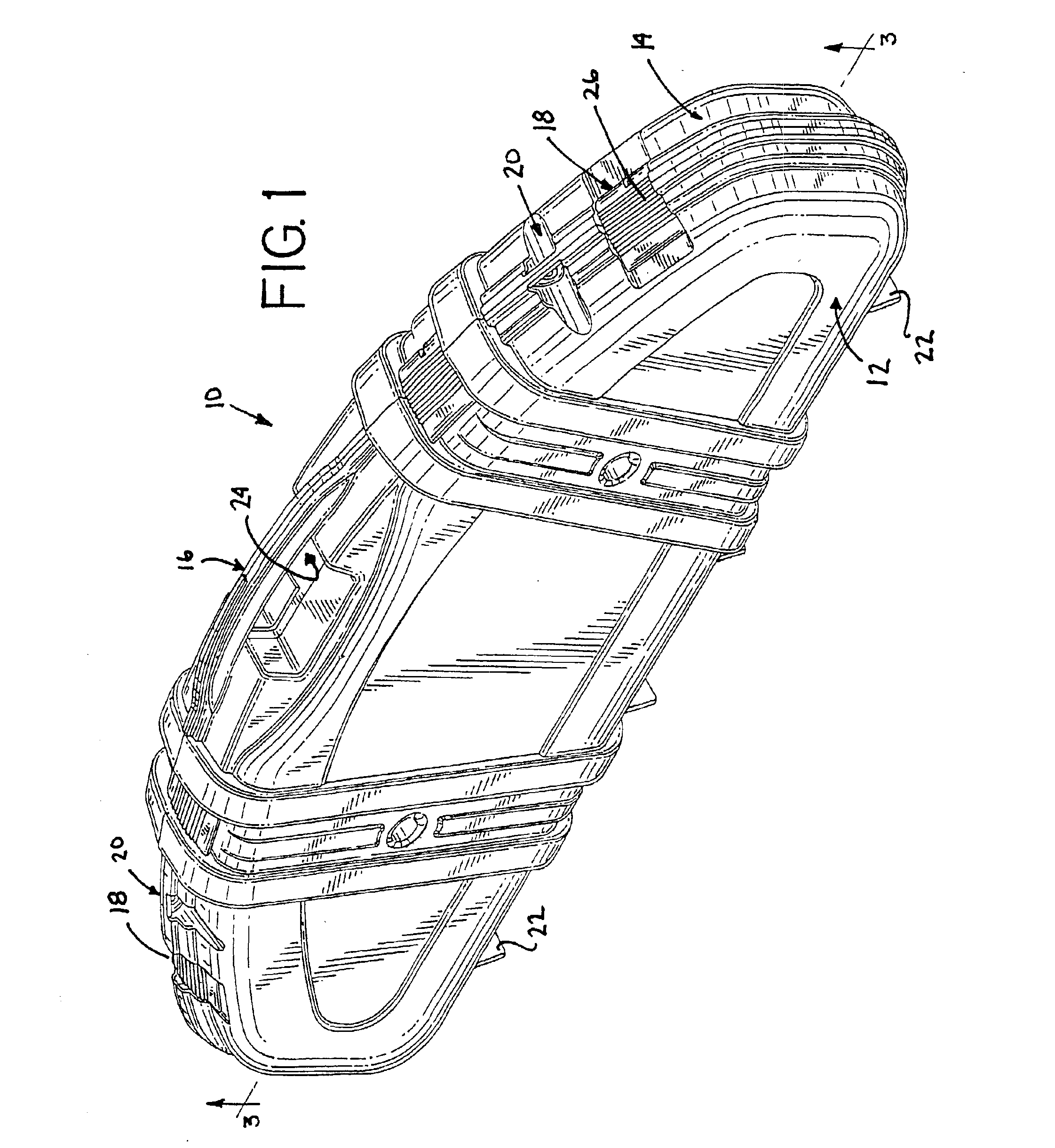
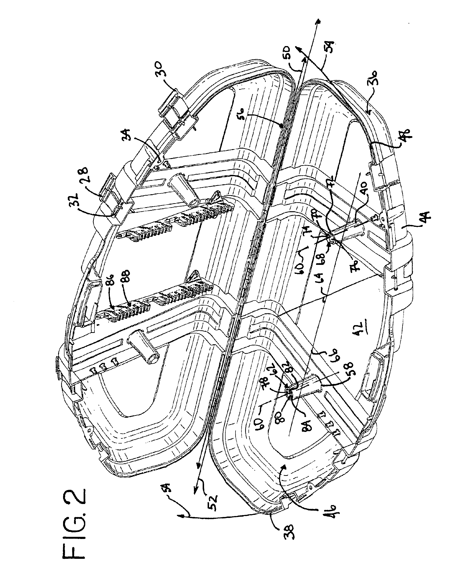
[0036]One embodiment of the present invention relates to a protective case for transporting and / or storing archery implements, preferably at least a bow and a plurality of arrows. Generally, the case 10 of this embodiment of the present invention, shown in FIGS. 1-5, includes interengaging case sections, a first case section 12 and a second case section 14 which are interconnected along a hinge line for movement between an open position, FIG. 2, and a closed position, FIGS. 1 and 3. As shown in FIG. 1, the case 10 also includes a handle 16, a plurality of latching devices 18, locking members 20, and a plurality of feet 22.

[0037]The handle 16 is formed by cooperation of the first case section 12 and the second case section 14. A passage 24 is defined below the handle 16 for receiving the hand or fingers of an operator in order to carry or move the case 10. Each latching device 18 in FIG. 2 includes an arm 26 and a catch 28. The arm 26 is removably secured to the case 10, and preferab...


PUM

PropertyMeasurementUnit
Timeaaaaaaaaaa
Heightaaaaaaaaaa

Abstract

A case for archery equipment includes, interengaging first and second case sections connected for relative movement between open and closed positions. The first and second case sections each include a wall for cooperatively defining an interior compartment when disposed in the closed position. The first and second case sections each including a set of reinforcing pillars which project into interior compartment. Each reinforcing pillar having a free end such that the free end of each reinforcing pillar affixed to the first case section is aligned with and engages the free end of one of the reinforcing pillars on the second case section. Each set of reinforcing pillars on the first and second case sections including at least one reinforcing pillar having an engaging contour including a first element portion and a complimentarily shaped second element portion.

Description

[0001]This is a continuation-in-part of application Ser. No. 10 / 120,194, filed Apr. 10, 2002, now abandoned, which is a continuation of application Ser. No. 09 / 694,187, filed Oct. 23, 2000 now U.S. Pat. No. 6,390,294.BACKGROUND OF THE INVENTION[0002]The present invention relates generally to a case for archery equipment, and more particularly, to a molded, protective case which is adapted for easy, low-cost mass production manufacture and which prevents damage to the equipment stored therein, by even distribution of loads and forces thereupon.[0003]Transporting archery equipment, such as bows and arrows, has historically been a difficult undertaking. By their very nature, archery equipment is large and cumbersome. The equipment is also delicate relative to its size. In particular, modern bows have very complex structure in order to provide the sophisticated functions now expected. While a bow may be disassembled for transportation, it is considered a major disadvantage if this is ne...

Claims


Application Information

Patent Timeline
IPC IPC(8): A63B71/00F41B5/00F41B5/14
CPCA63B71/0036F41B5/1457C08J7/123C08J2369/00Y10T292/0874
Inventor FIORE, JR., JOSEPH F.HAGEMANN, JOHN J.WHALEN, JOHN
Owner PLANO MOLDING CO LLC
Why Eureka
Try Eureka