
Intelligent networked fan assisted tiles for adaptive thermal management of thermally sensitive rooms

a networked fan and adaptive technology, applied in lighting and heating apparatus, ventilation systems, heating types, etc., can solve the problems of haphazard layout on the raised floor, insufficient intuitive air distribution, and complex cooling design in high-power density computer data centers, etc., to achieve well-balanced airflow and airflow well-balance

Inactive Publication Date: 2005-04-19
DEGREE CONTROLS
View PDF6 Cites 72 Cited by
  • Summary
  • Abstract
  • Description
  • Claims
  • Application Information

AI Technical Summary

Benefits of technology

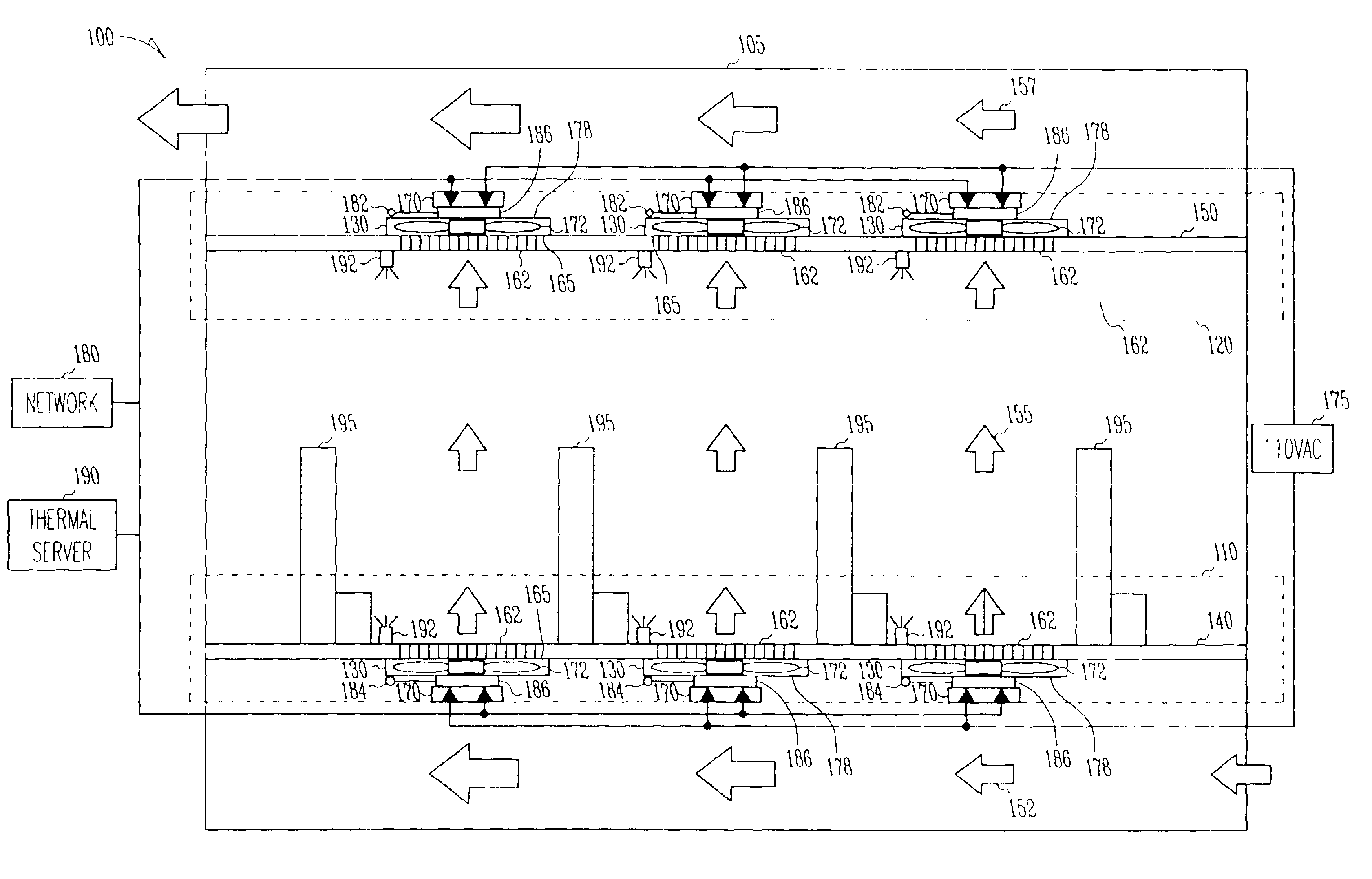
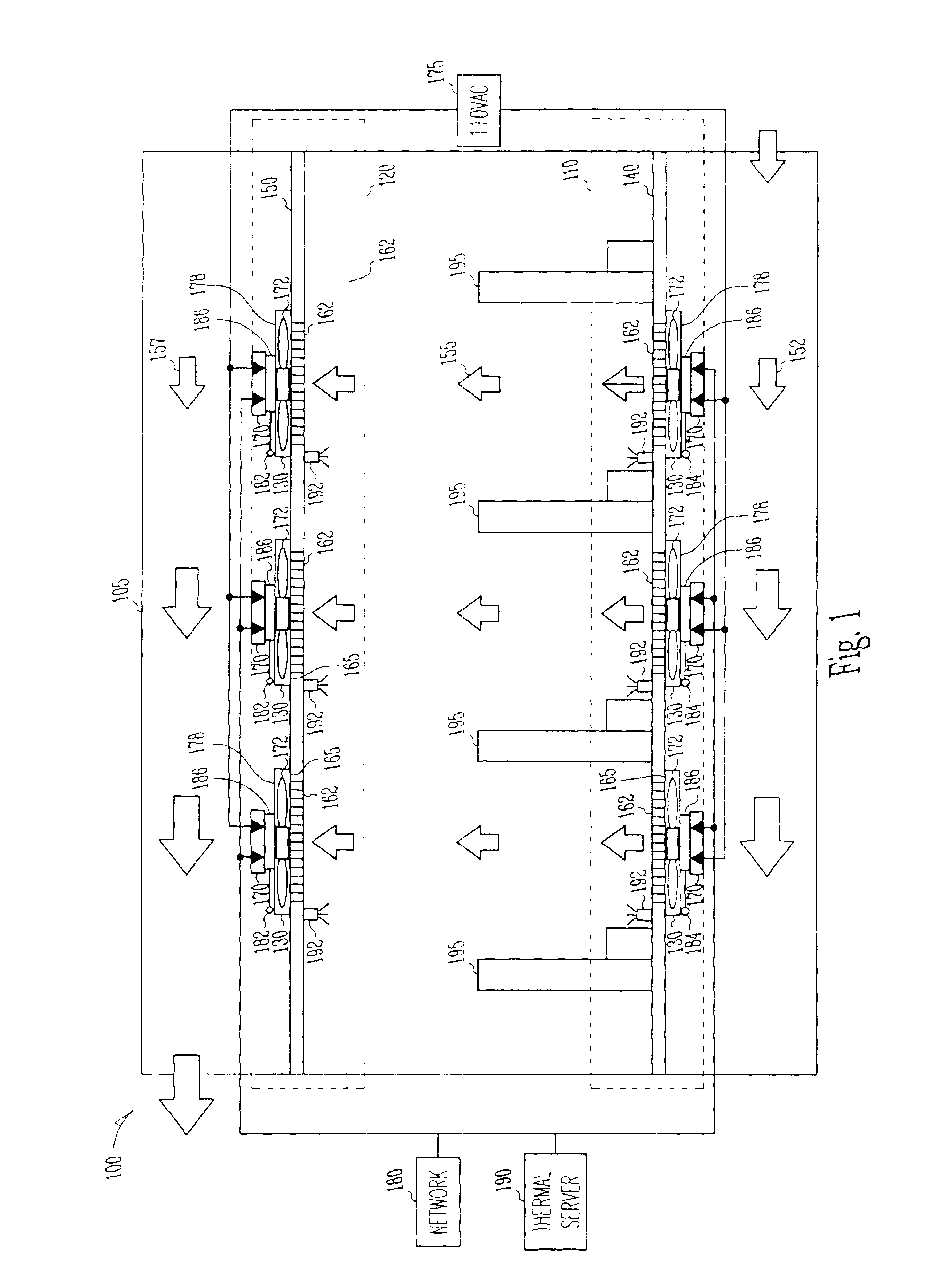
"The present invention provides a way to keep a computer data center cool and well-balanced. This is done by using multiple fans placed in the floor and ceiling of the center, which are connected to a computer that controls them based on airflow and temperature sensors. This results in a well-balanced airflow that helps to keep the center cool and comfortable for its occupants."

Problems solved by technology

Generally, cooling design in a high power density computer data center is quite complex.
Today's intuitive distribution of air does not suffice in providing a well-balanced airflow in a computer data center such that every location in the computer data center receives a uniform airflow to improve operating efficiency and cooling performance.
In addition, many of the computer data centers are hastily planned and implemented as the needed equipment must be quickly installed on a rush schedule.
The typical result is a somewhat haphazard layout on the raised floor that can have disastrous consequences due to environmental temperature disparities.
Unfortunately, the dangers of this lack of planning are, is not apparent until after serious reliability problems have already occurred.
Further, any changes in a computer data center due to traffic patterns, equipment changes and additions, blocked filters, failed fans, and so on can affect thermal load distribution, which in turn can affect the well-balanced airflow in a computer data center.

Method used


Image

  • Intelligent networked fan assisted tiles for adaptive thermal management of thermally sensitive rooms
  • Intelligent networked fan assisted tiles for adaptive thermal management of thermally sensitive rooms
  • Intelligent networked fan assisted tiles for adaptive thermal management of thermally sensitive rooms

Examples


Embodiment Construction

[0009]The present subject matter provides a technique for providing a well-balanced airflow in a room. The technique further provides a dynamic airflow balancing and thermal management for a computer data center.

[0010]In the following detailed description of the embodiments of the invention, reference is made to the accompanying drawings that form a part hereof, and in which are shown by way of illustration specific embodiments in which the invention may be practiced. These embodiments are described in sufficient detail to enable those skilled in the art to practice the invention, and it is to be understood that other embodiments may be utilized and that changes may be made without departing from the scope of the present invention. The following detailed description is, therefore, not to be taken in a limiting sense, and the scope of the present invention is defined only by the appended claims. The terms “thermal server”, “host computer”, “remote server”, and “remote computer” are u...


PUM


Abstract

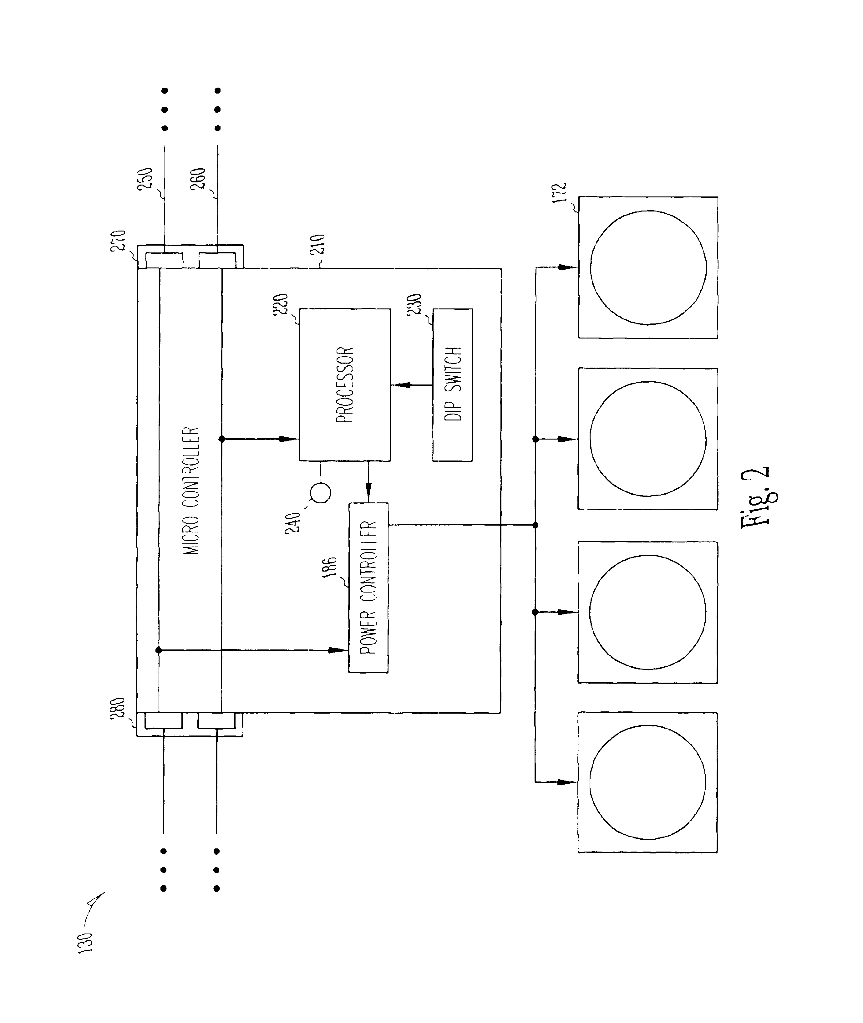
A technique to provide well-balanced airflow in a computer data center that uses fan assisted tiles coupled to a host computer through a network. In an example embodiment, this is accomplished by disposing the fan tiles, including temperature and airflow sensors and a programmable switch to provide a Network address, in multiple locations in raised floor and ceiling of the computer data center. Further, the example embodiments includes coupling the fan tiles to the host computer through the network to control the fan tiles based on the feedback received from the temperature and airflow sensors to provide adaptive airflow balancing and thermal management in the computer data center.

Description

TECHNICAL FIELD OF THE INVENTION[0001]The present invention relates generally to thermal management of thermally sensitive rooms, and more particularly to thermal management of a computer data center.BACKGROUND OF THE INVENTION[0002]The computer data centers typically, consist thousands of racks each with multiple computing units. The computing units can include multiple microprocessors, each dissipating approximately 250 W of power. The heat dissipation from a rack containing such computing units can exceed 10 KW. Today's computer data center, with about 1000 racks and occupying over 30,000 square feet can require about 10 MW of power for the computing infrastructure. A 100,000 square foot computer data center of tomorrow can require 50 MW of power for the computing infrastructure. Energy required to dissipate this heat can be an additional 20 MW. A hundred thousand square foot planetary scale computer data center, with five thousand 10 KW racks, can cost about 44 million dollars p...

Claims


Application Information

Patent Timeline
Patent Type & Authority Patents(United States)
IPC IPC(8): F24F11/00H05K7/20
CPCF24F11/0001F24F11/0009H05K7/20745H05K7/20836F24F11/0012F24F11/0079Y02B30/746F24F2011/0067F24F2221/40F24F2011/0038F24F11/30F24F2110/10F24F2110/30F24F11/54F24F11/77Y02B30/70F24F11/38F24F11/56
Inventor NAIR, RAJESH M.
Owner DEGREE CONTROLS
Learn More