Collecting device for suspended particles

a collection device and particle technology, applied in auxillary pretreatment, instruments, separation processes, etc., can solve the problems of difficult observation of particles, substantially impossible to analyze collected particles, and difficult to extract collected particles from filters, etc., to achieve the effect of easy analysis

Inactive Publication Date: 2005-04-19
SHIMADZU CORP
View PDF32 Cites 18 Cited by
  • Summary
  • Abstract
  • Description
  • Claims
  • Application Information

AI Technical Summary

Benefits of technology

[0011]In the present invention, the collecting container is provided with a discharge electrode and a collecting electrode, and is connected to an outlet of the mobility analyzer. After being charged by the single polar ions from the discharge electrode, the particles are collected on the collecting electrode. Therefore, according to the present invention, the particles with the particle diameter only in a predetermined range can be collected effectively on the collecting electrode. Also, it is easy to extract the collected particles. Therefore, according to the invention, the particles with the particle diameters only in a specific range among all the particles suspended in the gas can be easily analyzed by various types of analytical instruments and be examined with a microscope.

Problems solved by technology

In the conventional method of collecting the particles suspended in the gas using the filter, it is difficult to extract the collected particles from the filter.
In that case, it is difficult to observe the particles because images of the particles become a blur due to the filter as a background.
Further, when the collected particles are subjected to chemical analysis with various types of analytical instruments, it is substantially impossible to analyze the collected particles because it is difficult to separate an individual particle from the filter.
However, the proposed device collects all the particles in the gas, and can not selectively collect particles with diameters in a specific range.

Method used


Image

  • Collecting device for suspended particles
  • Collecting device for suspended particles

Examples


Embodiment Construction

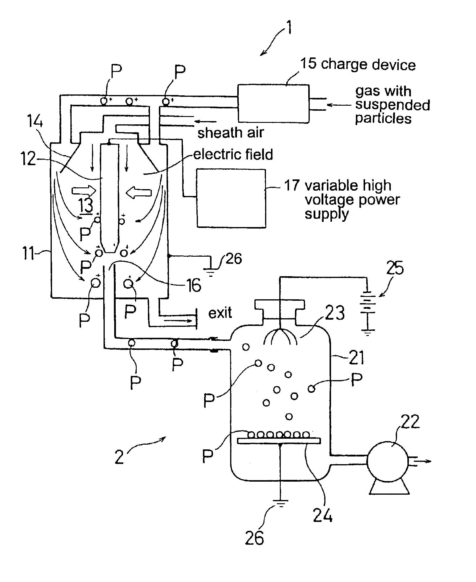
[0013]Hereunder, embodiments of the present invention will be described with reference to the accompanying drawing. FIG. 1 is a diagram showing a configuration of the preferred embodiment of the invention.

[0014]An electrode 12 constructing an inside cylinder is disposed along a shaft center inside an outside cylinder 11. A space between the electrode 12 and the outside cylinder 11 forms a passage 13 for flowing charged particles P and a gas.

[0015]A conical guide plate 14 is disposed at an upper end of the outside cylinder 11, so that clean sheath air A flows inside the guide plate 14. A charge device 15 supplies the gas including the suspended particles P through outside the guide plate 14. Also, a passage exit 16 formed of a narrow tube is provided at a lower end of the outside cylinder 1. The electrode 12 is connected to a variable high-voltage power supply 17 so that a specific negative high voltage can be applied to the electrode. The outside cylinder 11 is connected to an earth...


PUM

PropertyMeasurementUnit
sizesaaaaaaaaaa
electric field intensityaaaaaaaaaa
electric fieldaaaaaaaaaa

Abstract

A collecting device for collecting suspended particles includes a mobility analysis device; a collecting container connected to an outlet of the mobility analysis device; a discharge electrode disposed inside the collecting container for charging the particles inside the collecting container by generating single polar ions; and a collecting electrode for collecting the charged particles inside the collecting container by an electric potential difference relative to the discharge electrode. In the mobility analysis device, the particles are charged and guided into a flow path. An electric field is created in the flow path, and the particles are guided into the path perpendicular to the electric field. Since a mobility of a particle in an electric field depends on a size of the particle, the particles guided in the path are separated according to the electric field, thereby obtaining particles with sizes in a specific range.

Description

BACKGROUND OF THE INVENTION AND RELATED ART STATEMENT[0001]The present invention relates to a collecting device for suspended particles.[0002]For collecting particles suspended in a gas such as the atmosphere, a conventional method wherein a gas is sucked to pass through a filter so that particles in the gas are collected has been used widely.[0003]The inventor has proposed a device for collecting suspended particles in the atmosphere. The device includes a collecting container for sucking the atmosphere therein with a pump; a discharge electrode for generating single polar ions inside the collecting container; and a collecting electrode having a potential difference relative to the discharge electrode. The collecting device charges the particles suspended in the atmosphere sucked inside the collecting container, thereby collecting the particles on the collecting electrode.[0004]In the conventional method of collecting the particles suspended in the gas using the filter, it is diffi...

Claims


Application Information

Patent Timeline
Patent Type & Authority Patents(United States)
IPC IPC(8): B03C3/02B03C3/011B03C3/00B03C3/09B03C3/155B03C3/36B03C3/04B03C3/34G01N15/02G01N1/02
CPCB03C3/011B03C3/025B03C3/36B03C3/155B03C3/09
Inventor TOTOKI, SHINICHIRO
Owner SHIMADZU CORP
Why Eureka
Try Eureka