Amorphous carbon coated tool and fabrication method thereof

a technology of carbon coating and tool, applied in the field of tools, can solve the problems of increasing the cutting resistance, increasing the wear of the tool used on such specific workpieces, and increasing the wear of the tool at the cutting edge, and achieve the effect of high heat conductivity

Inactive Publication Date: 2005-04-19
SUMITOMO ELECTRIC HARDMETAL CORP +1
View PDF26 Cites 33 Cited by
  • Summary
  • Abstract
  • Description
  • Claims
  • Application Information

AI Technical Summary

Benefits of technology

[0015]In view of the foregoing, a main object of the present invention is to provide an amorphous carbon coated tool less vulnerable to adhesion of residual and chipping at the cutting edge when used in cutting soft metal, non-ferrous metal, organic material, material including hard particles, printed circuit boards, and in bi-metallic cutting of iron base material and soft metal material, and having temperature increase at the cutting edge suppressed by coating with amorphous carbon that has high heat conductivity to allow usage even under a severe cutting environment such as in dry cutting and high speed machining.

Problems solved by technology

In the case where the workpiece includes soft metal such as aluminum alloy, a non-ferrous metal such as titanium, magnesium, or copper, an organic material, or a material including hard particles such as graphite, or in the case of working on a printed circuit board or bimetallic cutting of an iron type material and aluminum, problems are noted such as residuals adhering to the cutting edge of the cutting tool to increase the cutting resistance, and, in some cases, cause chipping at the cutting edge.
The wear of the tool used on such specific workpieces has become more significant.
Since diamond is the hardest available material, grinding of a diamond film requires the usage of diamond that is extremely expensive.
This attributes to the increase in cost.
There was a problem that the fabrication cost including the coating process is extremely high.
As to tools made by brazing a diamond sintered compact on a base, it is difficult to fabricate the tools of complicated shape or the tools as fine as several millimeters in diameter.
Such a coated film is not suitable for usage in a severe cutting environment.

Method used


Image

  • Amorphous carbon coated tool and fabrication method thereof
  • Amorphous carbon coated tool and fabrication method thereof
  • Amorphous carbon coated tool and fabrication method thereof

Examples


example 1

[0077]As the base, a φ8 mm drill made of WC base cemented carbide was prepared. This base includes 1% by mass of (Ta, Nb) C, and Co of a content indicated in Table 1 that will be described afterwards. The surface of this base was subjected to the well-known cathode arc ion plating method, whereby Samples 1-38 of amorphous carbon coated drills of the present invention shown in Table 1-Table 4 were prepared.

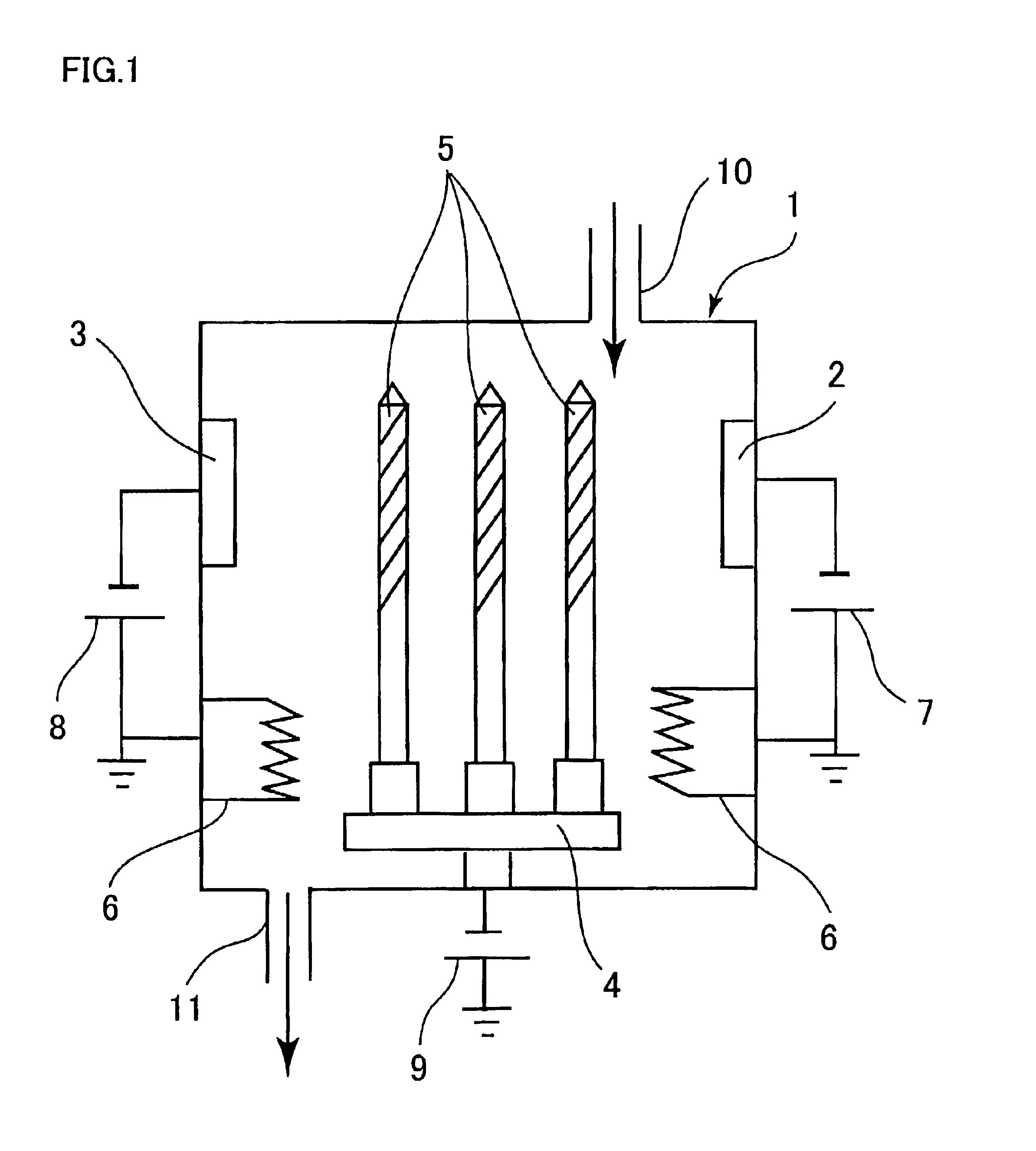
[0078]Referring to FIG. 1, a plurality of targets 2 and 3 are disposed in a film deposition apparatus 1. A drill formed of cemented carbide is attached to a base holder 4 that rotates between targets about the center point of respective targets. Power supplies 7 and 8 are adjusted to alter the discharging current of the cathode to coat amorphous carbon while controlling the vaporization of the target material.

[0079]The vacuum level in deposition apparatus 1 was set to an atmosphere of 2×10⁻³ Pa while heating up to 100° C. using a base heater 6. Argon gas is then introduced. A volta...

example 2

[0093]By means of a method identical to that of Example 1, the surface of a φ4 mm reamer made of cemented carbide was coated with an amorphous carbon film (film of Sample 2). The cemented carbide base of Example 2 includes 1% by mass of (Ta, Nb) C, and 7% by mass of Co. The hydrogen content in the amorphous carbon film is not more than 5 atomic %. As comparative examples, a hydrogenated amorphous carbon film by CVD (Comparative Example 4), a TiN film (Comparative Example 5) and a TiAlN film (Comparative Example 6) were deposited. Each of the surface coated reamers fabricated by the above-described method were used in the boring process of an aluminium die cast (ADC12) under the conditions shown in Table 8. The number of bores produced and the status of the cutting edge were evaluated.

[0094]

TABLE 8WorkpieceADC12materialCutting speed230 m / minFeed0.15 mm / revDepth15 mm

[0095]The composition of ADC12 in Table 8 is defined in the standards of JIS H5302.

[0096]Variation in the diameter of bo...

example 3

[0098]The surface of a φ7 mm end mill made of cemented carbide was coated with an amorphous carbon film (film of Sample 3 of the present invention), fabricated by a method identical to that of Example 1. The cemented carbide base contains 1% by mass of (Ta, Nb) C and 7% by mass of Co. The hydrogen content in the amorphous carbon film is not more than 5 atomic %. As comparative examples, a hydrogenated amorphous carbon film by CVD (Comparative Example 4), a TiN film (Comparative Example 5), and a TiAlN film (Comparative Example 6) were deposited. Using each of the surface coated end mills fabricated by the above-described method, end milling is effected on an aluminium die cast (ADC12) under conditions shown in Table 9. The cutting length and the status of the cutting edge before deviation from the tolerance of the surface roughness of the workpiece were evaluated. In Table 9, Ad (axial depth of cut) is the depth of cut in the axial direction whereas Rd (radial depth of cut) is the d...


PUM

PropertyMeasurementUnit
thicknessaaaaaaaaaa
thicknessaaaaaaaaaa
thicknessaaaaaaaaaa

Abstract

An amorphous carbon coated tool includes a base material of WC base cemented carbide, and an amorphous carbon film formed on this base material. The cobalt content in the base material is at least 12% by mass. The maximum thickness of the amorphous carbon film is at least 0.05 μm and not more than 0.5 μm at the cutting edge. The amorphous carbon film is deposited with graphite as the source material by physical vapor deposition in an atmosphere substantially absent of hydrogen. The amorphous carbon film coated tool superior in wear resistance and adhesion resistance is preferably applicable to rotating tools such as drills, end mills and reamers, indexable inserts used for milling cutters and turning tools, and cutting-off tools such as cutters, knives, or slitters.

Description

CROSS-REFERENCE TO RELATED APPLICATION[0001]This application is related to U.S. application Ser. No. 10 / 167,751 filed Jun. 11, 2002.BACKGROUND OF THE INVENTION[0002]1. Field of the Invention[0003]The present invention relates to a tool having a wear-resistant and adhesion-resistant amorphous carbon film formed at the surface of rotating tools (drills, end mills, reamers, and the like), an indexable insert used for milling cutters and turning tools, and cutting-off tools (cutters, knives, slitters and the like). The present invention also relates to a method of fabricating such a tool.[0004]2. Description of the Background Art[0005]The conventional requirements with respect to cutting tools include the capability of increasing the lifetime of the tool by minimizing any damage at its surface and carrying out machining at high efficiency as well as finishing the workplace with high quality (maintaining the surface configuration, the hardness of the parent material, the dimension accura...

Claims


Application Information

Patent Timeline
Patent Type & Authority Patents(United States)
IPC IPC(8): C23C14/02C23C14/06C23C30/00C23C16/26
CPCC23C14/022C23C14/0605C23C30/005Y10T428/265Y10T428/24942Y10T428/24628Y10T428/30Y10T428/24975Y10T408/78Y10T407/27Y10T428/24479A63H1/20B65D85/60
Inventor OHTANI, SATOSHIOKAZAKI, NAOTOOGATA, KIYOSHIFUKUI, HARUYOIRIE, MIKIUTSUMI, YOSHIHARUOHARA, HISANORIMORIGUCHI, HIDEKIIKEGAYA, AKIHIKOTSUDA, KEIICHISETOYAMA, MAKOTO
Owner SUMITOMO ELECTRIC HARDMETAL CORP
Why Eureka
Try Eureka