Movable micro-electromechanical device

a micro-electromechanical and moving technology, applied in the direction of acceleration measurement using interia forces, instruments, nanoinformatics, etc., can solve the problems of affecting the ability to precisely control and monitor this relative motion, and other problems and limitations of existing computer storage and other mems devices, etc., to achieve the effect of reducing the stiffness of out-of-plane devices and reducing the stiffness

Inactive Publication Date: 2005-04-19
HEWLETT PACKARD DEV CO LP
View PDF7 Cites 23 Cited by
  • Summary
  • Abstract
  • Description
  • Claims
  • Application Information

AI Technical Summary

Benefits of technology

[0004]A movable system, such as a computer storage device, is provided including a frame, a mover configured to move relative to the frame, and a mechanical suspension operatively coupled between the frame and mover. The mechanical suspension typically is configured to permit planar movement of the mo

Problems solved by technology

In many cases, the configuration of the mechanical suspension greatly affects the ability to precisely control and monitor this relative motion.
Existing computer storage and other MEMS devices have various problems and limitations associated with the mechanical suspension used to interconnect the movable components.
Specifically, out-of-plane stiffness tends to decrease substantially in these devices the f

Method used


Image

  • Movable micro-electromechanical device
  • Movable micro-electromechanical device
  • Movable micro-electromechanical device

Examples


Embodiment Construction

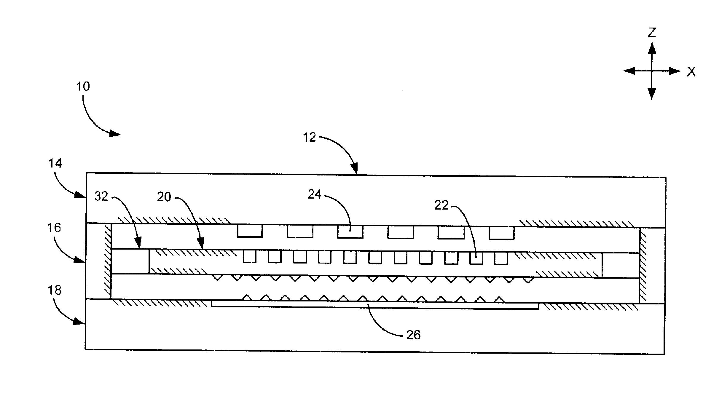
[0018]The present embodiments of the invention are directed to micro-electromechanical (MEMS) devices and other movable systems having an improved mechanical suspension configured to interconnect system components that move relative to one another. The movable systems described herein may be used in a variety of settings, but have proven particularly useful in very small computer storage devices. For purposes of illustration only, the movable system embodiments described below will be discussed primarily in the context of a high-density MEMS computer storage device.

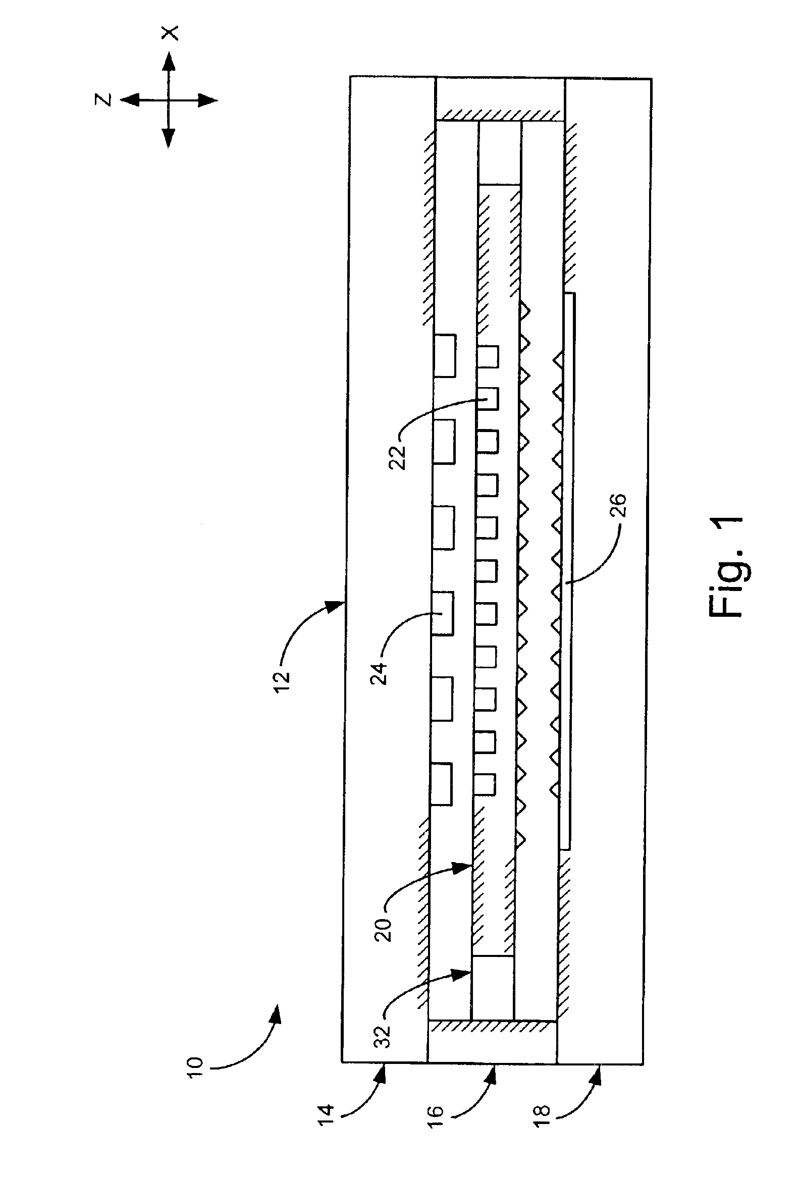
[0019]FIG. 1 shows a side cross-section view of a computer storage device 10, including a mechanical suspension. Device 10 typically is composed of a semiconductor material and may be formed using various fabrication techniques, including silicon wafer bonding and deep reactive ion etching. Device 10 includes a frame 12 having a top layer 14, middle layer 16, and bottom layer 18. Middle layer 16, also referred to as the m...


PUM


Abstract

A movable system, such as a computer storage device, having a frame, a mover configured to move relative to the frame, and a mechanical suspension operatively coupled between the frame and mover. The mechanical suspension is configured to permit planar movement of the mover while substantially preventing out-of-plane movement, and includes a first flexure configured to flex in response to movement of the mover in a first direction relative to the frame, and a second flexure configured to flex in response to relative movement occurring in a second direction.

Description

BACKGROUND OF THE INVENTION[0001]Micro-electromechanical (MEMS) devices having components configured to move relative to one another are widely known. An example of such a movable system is a computer storage device having a frame, mover, and a mechanical suspension interconnecting the frame and mover. Typically, the mechanical suspension holds the mover relative to the frame and allows for relative movement to occur between the mover and frame. Relative movement is achieved by applying a force to the frame and / or mover. In many cases, the applied force is provided by an actuator, such as an electrostatic drive located on the frame. The mechanical suspension typically includes flexing structures, referred to as flexures, that have spring-like characteristics. When an actuating force is applied, the mover is displaced relative to the frame from a resting or equilibrium position. When the actuating force is removed, the flexures urge the mover to return to the resting position. In dat...

Claims


Application Information

Patent Timeline
IPC IPC(8): G11B33/08G11B9/00G11B9/14G11B9/04
CPCB82Y10/00G11B33/08G11B9/1418G11B9/14
Inventor WALMSLEY, ROBERT GMILLIGAN, DONALD J
Owner HEWLETT PACKARD DEV CO LP
Why Eureka
Try Eureka