Dual antenna and radio device

Inactive Publication Date: 2005-04-19
PULSE FINLAND
View PDF14 Cites 76 Cited by
  • Summary
  • Abstract
  • Description
  • Claims
  • Application Information

AI Technical Summary

Benefits of technology

[0006]An advantage of the invention is that mutual interference of radio parts using separate antennas can be made relatively small without using an arrangement for electrical isolation between the antenna elements. This is based on the fact that the transmission power of the interfering antenna drops in the operating band of the other antenna. Another advantage of the invention is that it makes antenna filt

Problems solved by technology

An interfering antenna comprises structural parts which cause substantial degradation

Method used


Image

  • Dual antenna and radio device
  • Dual antenna and radio device
  • Dual antenna and radio device

Examples


Embodiment Construction

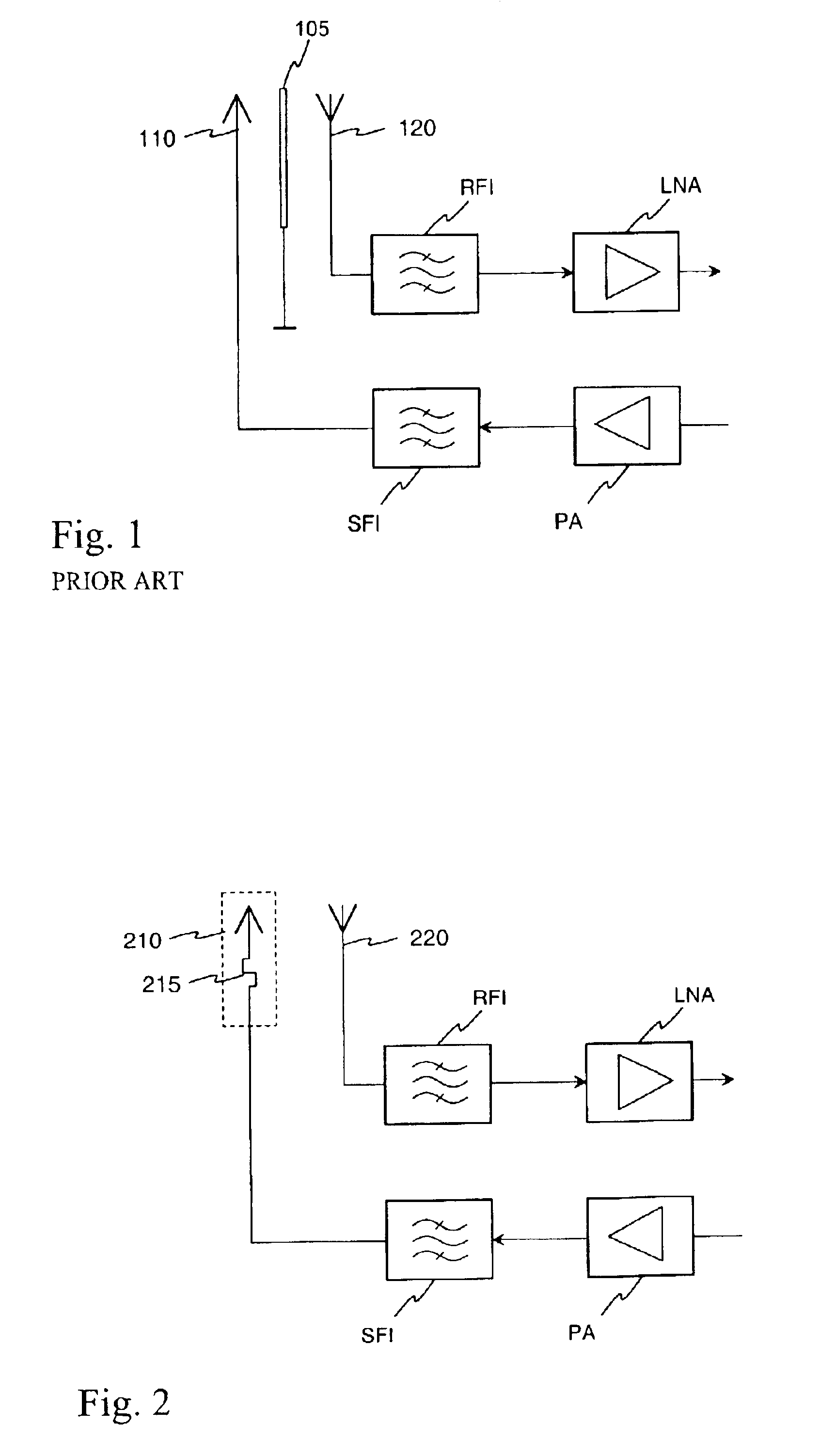
[0018]FIG. 1 was already discussed in connection with the description of the prior art.

[0019]FIG. 2 schematically shows an antenna isolation solution according to the invention. Like in FIG. 1, here, too, are shown the antenna end of a transmitter operating according to a first system, and the antenna end of a receiver operating according to a second system. The difference from FIG. 1 is that the electromagnetic isolation arrangement between the transmitting antenna 210 and receiving antenna 220 is now missing. Instead, FIG. 2 shows symbol 215 referring to an arrangement included in the transmitting antenna structure to provide electromagnetic isolation of the antennas. Isolation is realized such that the arrangement 215 causes substantial deterioration in the radiation characteristics of the transmitting antenna 210 in the operating band of the receiving antenna 220.

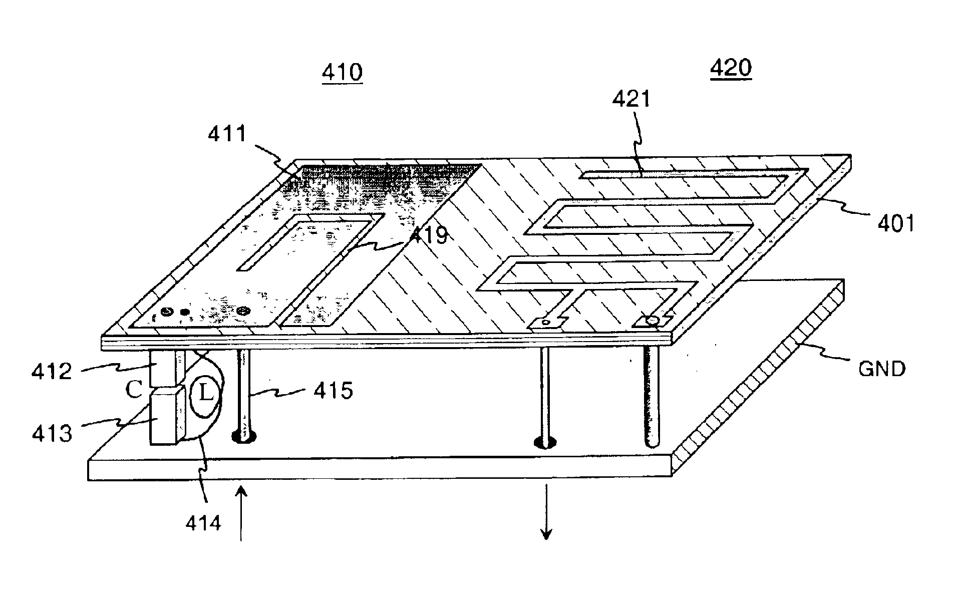
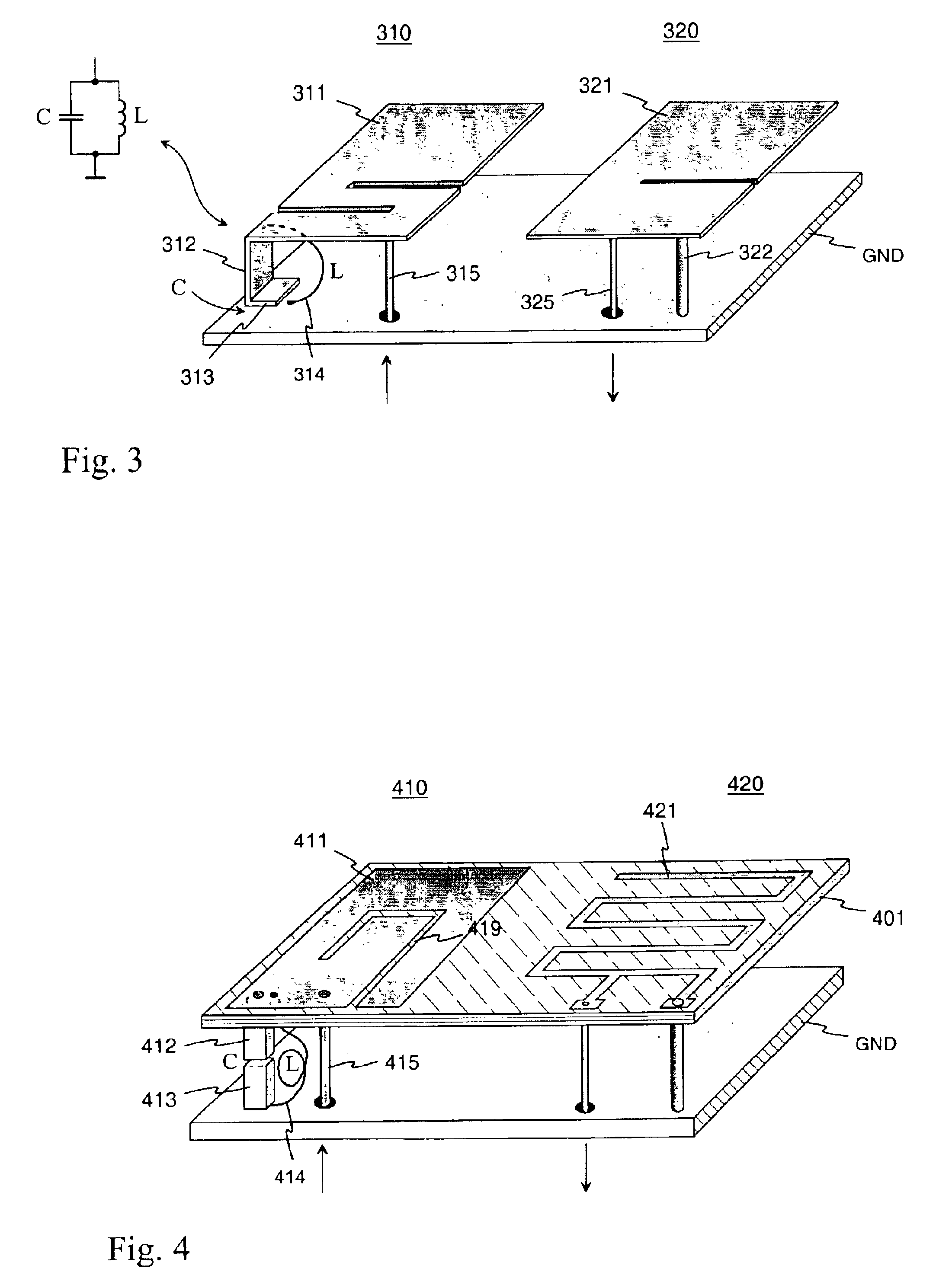
[0020]FIG. 3 shows an example of an antenna structure according to the invention. It includes two PIFA-type antennas ...


PUM


Abstract

An arrangement for enhancing electrical isolation between antennas in antenna structures comprising at least two antennas, and a radio device applying the arrangement. The interfering antenna comprises components causing substantial degradation in radiation characteristics in the operating band of another antenna. For example, a PIFA (310) may comprise, instead of a short-circuit conductor, a conductive structure (312, 313, 314) having a parallel resonance in the operating band of another antenna (320). Mutual interference of radio parts using separate antennas can be made relatively small without electrical isolation arrangements between antenna elements. Moreover, the invention makes antenna filter design easier and reduces disadvantages caused by antenna filters.

Description

FIELD OF THE INVENTION[0001]The invention relates to an arrangement for enhancing electrical isolation between antennas in antenna structures comprising at least two antennas. The invention also relates to a radio device employing a dual antenna according to the invention.BACKGROUND OF THE INVENTION[0002]Portable communications devices operating in two or more radio systems have become common in recent years. If such a communications device functions only in one system at a time, it is usually equipped with an antenna that has two operating bands or one band which is wide enough to cover both bands used by the two systems, for example. Two separate antennas may be used if the communications device can function simultaneously in two systems, especially if the frequency bands of the systems are relatively close to one another. With separate antennas, the mutual interference of the systems can be made smaller than with a common antenna. However, the mutual interference is not completel...

Claims


Application Information

Patent Timeline
IPC IPC(8): H01Q1/00H01Q1/52H01Q9/04
CPCH01Q9/0421H01Q1/525H01Q9/0442
Inventor KOSKINIEMI, KIMMOMIKKOLA, JYRKI
Owner PULSE FINLAND
Why Eureka
Try Eureka