Regenerative optical amplifier

a regenerative optical amplifier and amplifier technology, applied in the direction of laser arrangement, laser details, instruments, etc., can solve the problems of difficult to achieve symmetry in the rise and drop waveform of pulse voltage, placing restrictions on the control level, and complicated drive circuitry, etc., to achieve the effect of convenient operation

Inactive Publication Date: 2005-04-19
CYBER LASER
View PDF2 Cites 13 Cited by
  • Summary
  • Abstract
  • Description
  • Claims
  • Application Information

AI Technical Summary

Benefits of technology

[0023]According to the present invention as described above, a first polarizing element for injecting input light to a resonator is driven continuously, and a second polarizing element is driven to extract the amplified light from the resonator, so that there is no need to quickly shut off (drop off) the voltages applied to the respective polarizing elements, and there is no need to repeatedly apply voltage to a single polarizing element at high speed. As a result, the application of voltage to a polarizing element such as a Pockels cell can be performed easily without requiring complicated drive circuits, and the amplification time in the resonator can be flexibly and precisely controlled, so as also to allow a light amplification operation to be repeated at high speed.

Problems solved by technology

Thus, regenerative optical amplifiers using Pockels cells involve the problem of how to apply a high voltage on the order of kV to the Pockels cells in the short span of a few ns, complicating the drive circuitry (control circuits for the applied voltage) required for these Pockels cells.
Moreover, it is very difficult to achieve symmetry in the rise and drop waveforms of the pulse voltages.
Therefore, an amplification time TAT on the order of a few hundred ns must be selected although this is more than is actually required, thereby placing restrictions on the level of control allowed for the amplification time TAT, and making it difficult to control the amplification time TAT with precision.
For this reason, not only do the drive circuits of Pockels cells require high-voltage power sources with quickly rising and falling output, but the high-voltage power sources also need to be capable of responding to high-speed repetitive operation on the order of a few tens of kHz, thus making it very difficult in actual practice to achieve a drive circuit for Pockels cells.
However, this structure is no different from the regenerative optical amplifier at least in that a high voltage on the order of kV lasting only a few ns must be applied in order to drive the respective Pockels cells, thus making it difficult to achieve a drive circuit for the Pockels cells.
In particular, complicated circuitry is needed to achieve a fast rise time, thus leaving unsolved the problem of how to make a suitable drive circuit for the Pockels cell.
Additionally, once the applied voltage has quickly risen, the amplification time will last until the voltage quickly drops away, thus requiring restrictions on the control of the amplification time just as in the regenerative optical amplifier of FIG. 5, and making it difficult to increase the speed of the repetitive operation of the optical amplifier.

Method used


Image

  • Regenerative optical amplifier
  • Regenerative optical amplifier
  • Regenerative optical amplifier

Examples


first embodiment

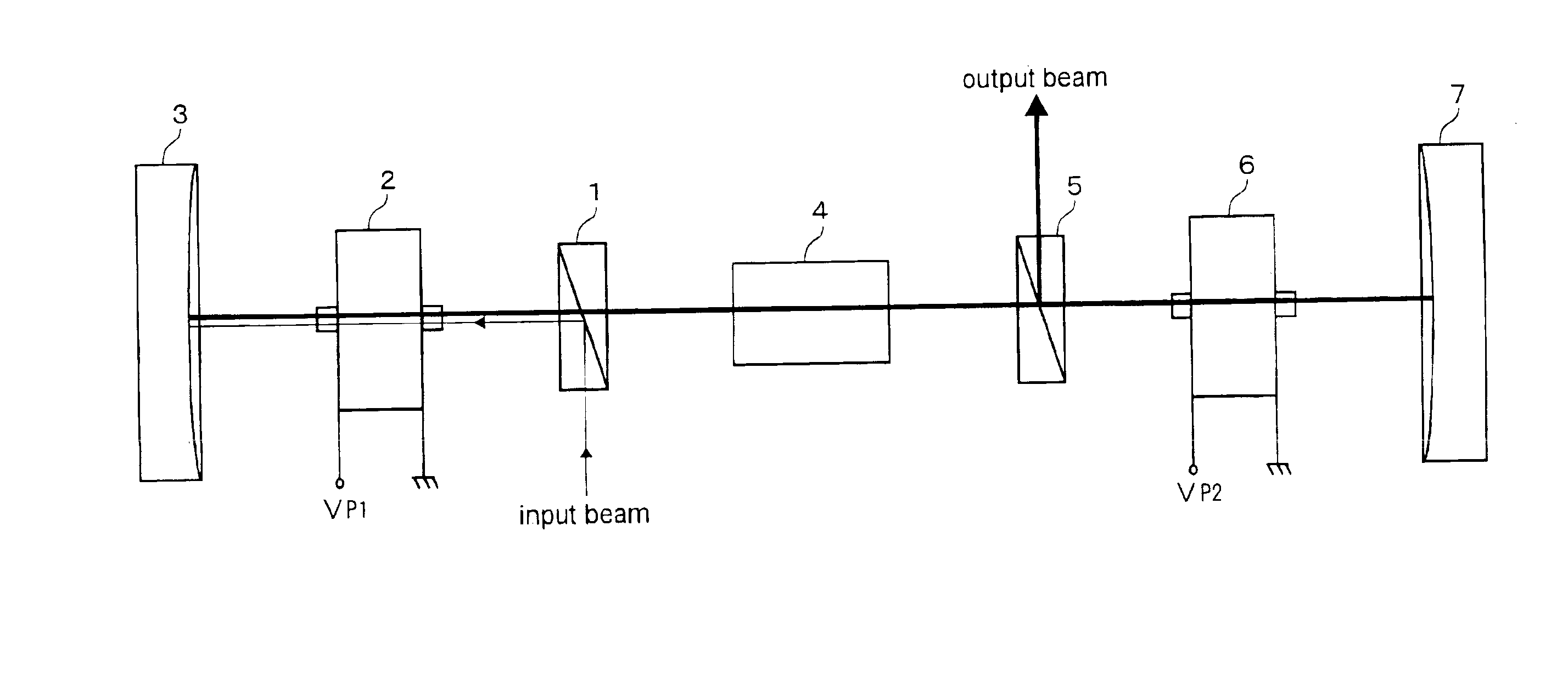
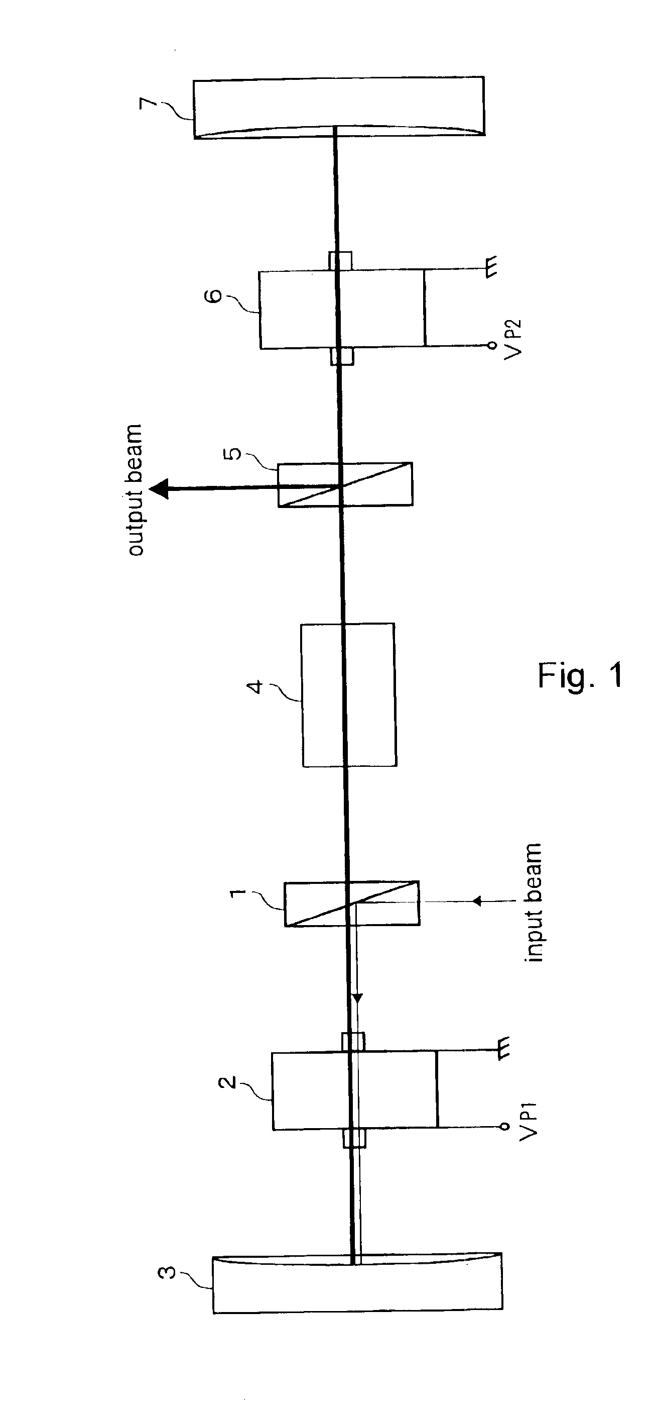
[0030]Herebelow, embodiments of the present invention shall be described with reference to the drawings. FIG. 1 is a diagram showing the structure of a regenerative optical amplifier according to the present invention.

[0031]When a voltage is applied to a Pockels cell such that the polarization of a laser light pulse is rotated by 90 degrees with each passage through the Pockels cell, the direction of polarization will be rotated by a total of 180 degrees upon passing twice through the Pockels cell, thus restoring the original polarization. Therefore, two Pockels cells are used, with voltage being applied to only the first Pockels cell. As a result, the polarization of a light pulse which has passed twice through the two Pockels cells will be rotated by 90 degrees. Next, if voltage is applied to both the first and second Pockels cells, the polarization of the light pulse will rotate by 180 degrees. As a result, the polarization of the light pulse becomes the same as the polarization ...

second embodiment

[0059]FIG. 3 is a diagram showing the structure of a regenerative optical amplifier according to the present invention. The regenerative optical amplifier of the present embodiment (hereinafter referred to as “present regenerative optical amplifier” in this ), as shown in the drawing, comprises a polarizer 1, a Pockels cell 2, a reflective mirror 3, a laser crystal 4, a polarizer 5, a Pockels cell 6, a reflective mirror 7 and a quarter-wave plate 8.

[0060]Among these components, the polarizer 1, Pockels cell 2, reflective mirror 3, laser crystal 4, polarizer 6 and reflective mirror 7 are physically identical to the components of the above-described first embodiment, so that they will be indicated by the same reference numbers as in the first embodiment and their respective descriptions shall be omitted, but they functionally perform effects which are specific to the present embodiment. While the details will be made clear in the below-given description of the functions, it is possibl...


PUM

PropertyMeasurementUnit
lengthaaaaaaaaaa
timeaaaaaaaaaa
timeaaaaaaaaaa

Abstract

The invention offers a regenerative optical amplifier enabling voltage to be easily applied to polarizing elements such as Pockels cells, without the need for complicated drive circuitry. An input beam of S-polarized light is reflected by a polarizer 1 and advances to a Pockels cell 2. In the time it takes for the input beam, having once passed through the Pockels cell 2, to be reflected by a reflective mirror 3 and return to the Pockels cell 2, a voltage VP1 causing a 90-degree rotation in the polarization of transmitted light is applied to the Pockels cell 2, and this applied voltage VP1 is maintained. The input beam is converted by the Pockels cell 2 into a P-polarized light pulse which is transmitted by the polarizer. Subsequently, the light pulse is converted from P-polarized light to S-polarized light and back to P-polarized light with each roundtrip of the Pockels cell 2, while passing each time between the reflective mirror 3, laser crystal 4 and reflective mirror 7, so as to be amplified in the resonator formed thereby. The amplified light pulse is extracted by applying a voltage VP2 causing a 90-degree rotation of the polarization of the transmitted light to the Pockels cell 6 to convert the light pulse to S-polarized light which is then reflected out of the resonator by the polarizer 5.

Description

BACKGROUND OF THE INVENTION[0001]The present invention relates to a regenerative optical amplifier having a resonator for amplifying light, and using a polarizing element driven by the application of voltage.[0002]Regenerative amplifiers are amplifying devices that trap pulses of light supplied from a laser light source in a resonator for amplification, and extract the amplified light pulses from the resonator to obtain high-power light pulses. Polarizing elements such as Pockels cells driven by application of voltage are often used in order to trap and extract the light pulses. Pockels cells are polarizing elements that are driven by the application of voltage to crystals exhibiting the Pockels effect, in which the optical properties of the crystal can be made to become anisotropic with the application of voltage, thereby changing the state of polarization of the light passing through the crystal. In regenerative amplifiers making use of Pockels cells, the use of polarizers and the...

Claims


Application Information

Patent Timeline
Patent Type & Authority Patents(United States)
IPC IPC(8): H01S3/23H01S3/106H01S3/107G02F1/03
CPCH01S3/235H01S3/1075
Inventor TAMAKI, YUSUKETAKASAGO, KAZUYAMIURA, TAISUKESEKITA, HITOSHI
Owner CYBER LASER
Why Eureka
Try Eureka