
Swivel hinge with angular fixing structure

a technology of fixing structure and hinge, which is applied in the direction of instruments, portable computer details, electrical apparatus casings/cabinets/drawers, etc., can solve the problems that the elastic ring cannot be disposed between the fixture friction ring and the rotation friction ring, and achieve the effect of stable input and display environmen

Inactive Publication Date: 2005-04-26
QUANTA COMPUTER INC
View PDF8 Cites 87 Cited by
  • Summary
  • Abstract
  • Description
  • Claims
  • Application Information

AI Technical Summary

Benefits of technology

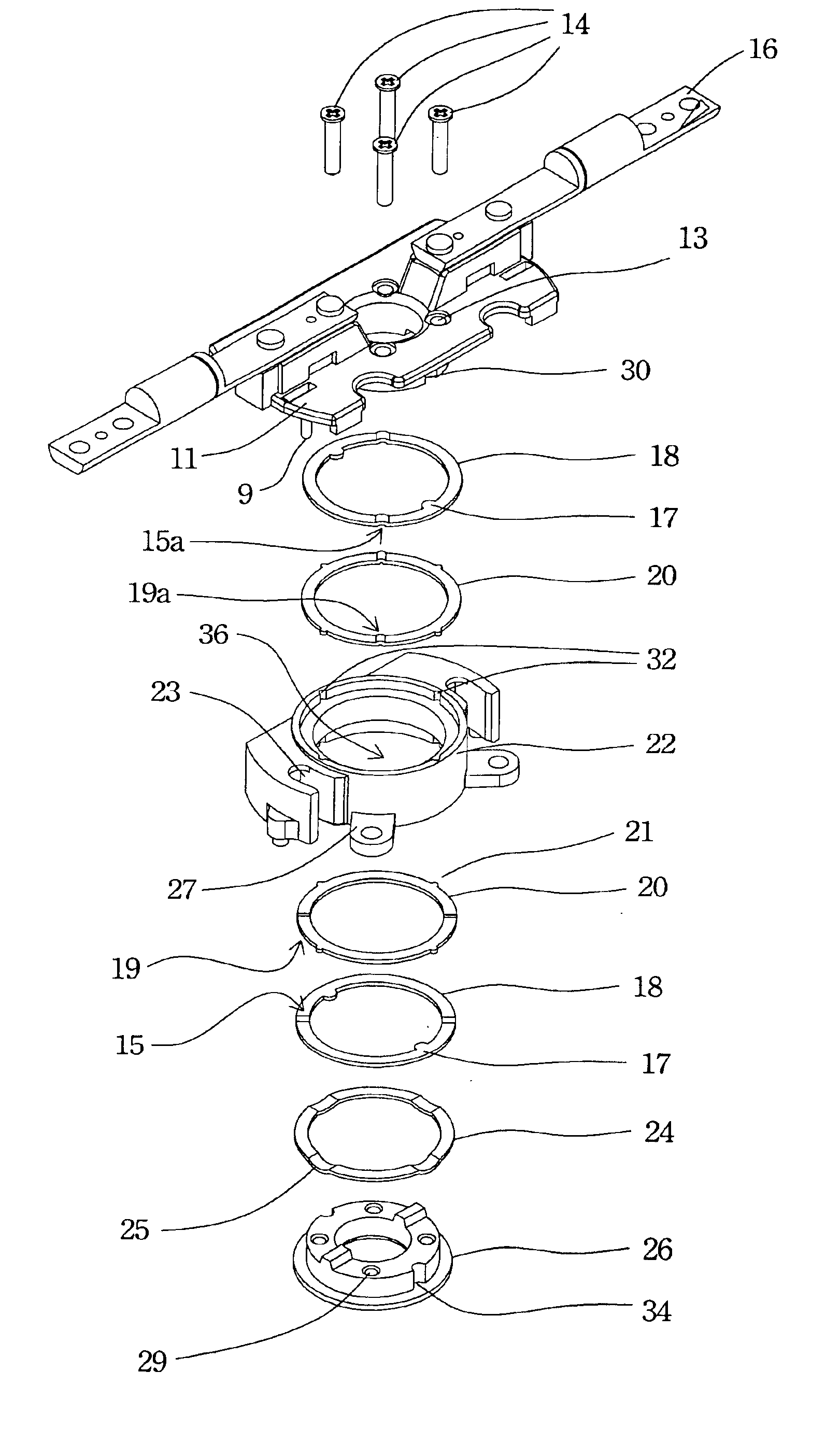
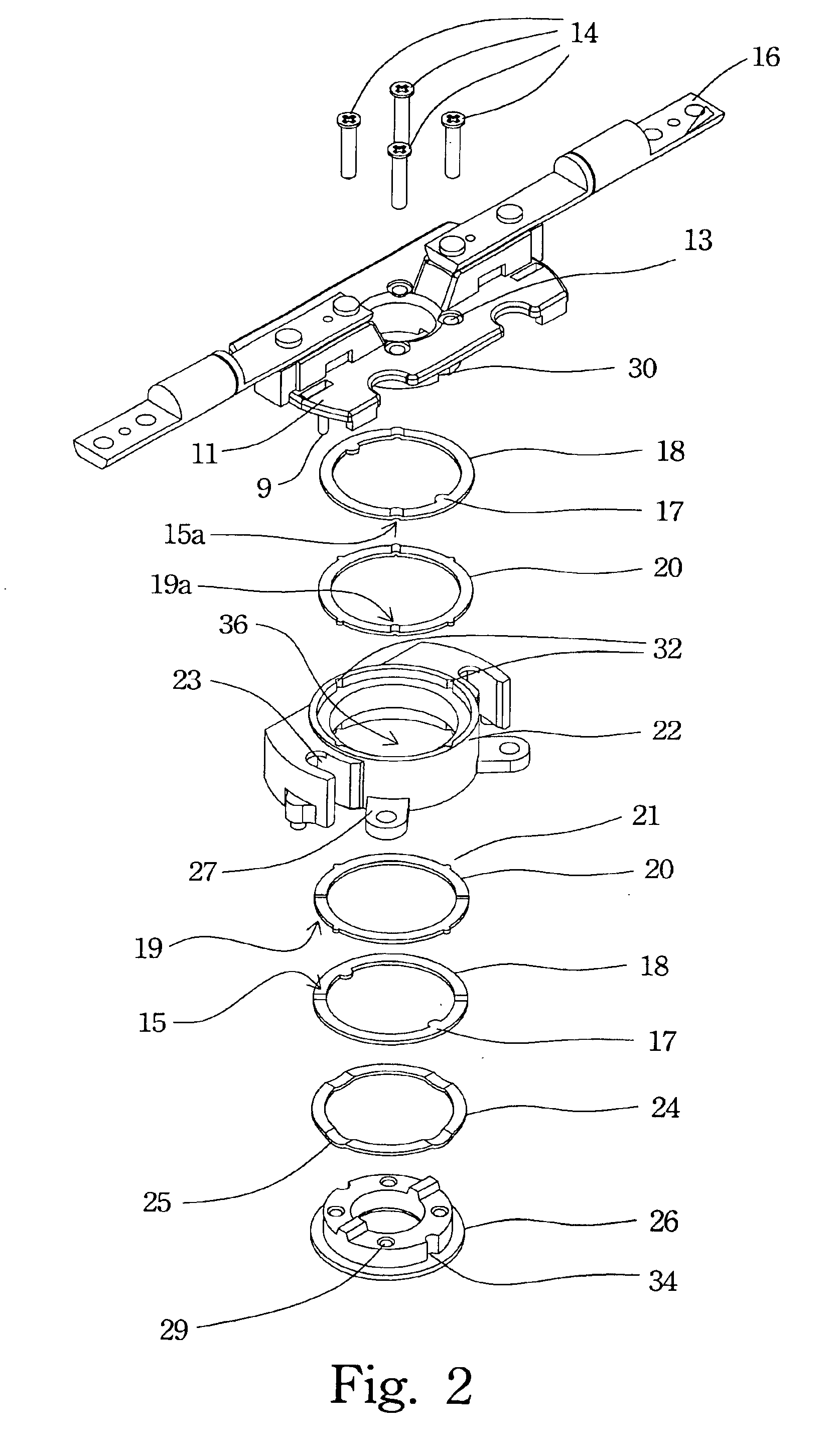
The present invention provides a swivel hinge apparatus with an angular fixing function for a notebook computer. The apparatus includes a fixture part, a fixture friction ring, a rotation part, a rotation friction ring, and an elastic ring. The fixture part is mounted on the mainframe and has a through hole in the center. The fixture friction ring is fixed on the fixture part and has at least one holder on the surface. The rotation friction ring is fixed on the rotation part and has at least one slot in the surface. The elastic ring is located between the fixture part and the fixture friction ring. The rotation part includes a rotation plate and a rotation base. The rotation plate connects to the rotation base via the through hole of the fixture part. The fixture friction ring alternatively has at least one slot, and the rotation friction ring alternatively has at least one holder. The elastic ring can be disposed between the rotation friction ring and the rotation part or between the fixture friction ring and the rotation part. The swivel hinge apparatus can provide a multi-angle fixing function and a steady input and display environment for users.

Problems solved by technology

But the elastic ring cannot be disposed between the fixture friction ring and the rotation friction ring.

Method used


Image

  • Swivel hinge with angular fixing structure
  • Swivel hinge with angular fixing structure
  • Swivel hinge with angular fixing structure

Examples


Embodiment Construction

[0020]Reference will now be made in detail to the present preferred embodiments of the invention, examples of which are illustrated in the accompanying drawings. Wherever possible, the same reference numbers are used in the drawings and the description to refer to the same or like parts.

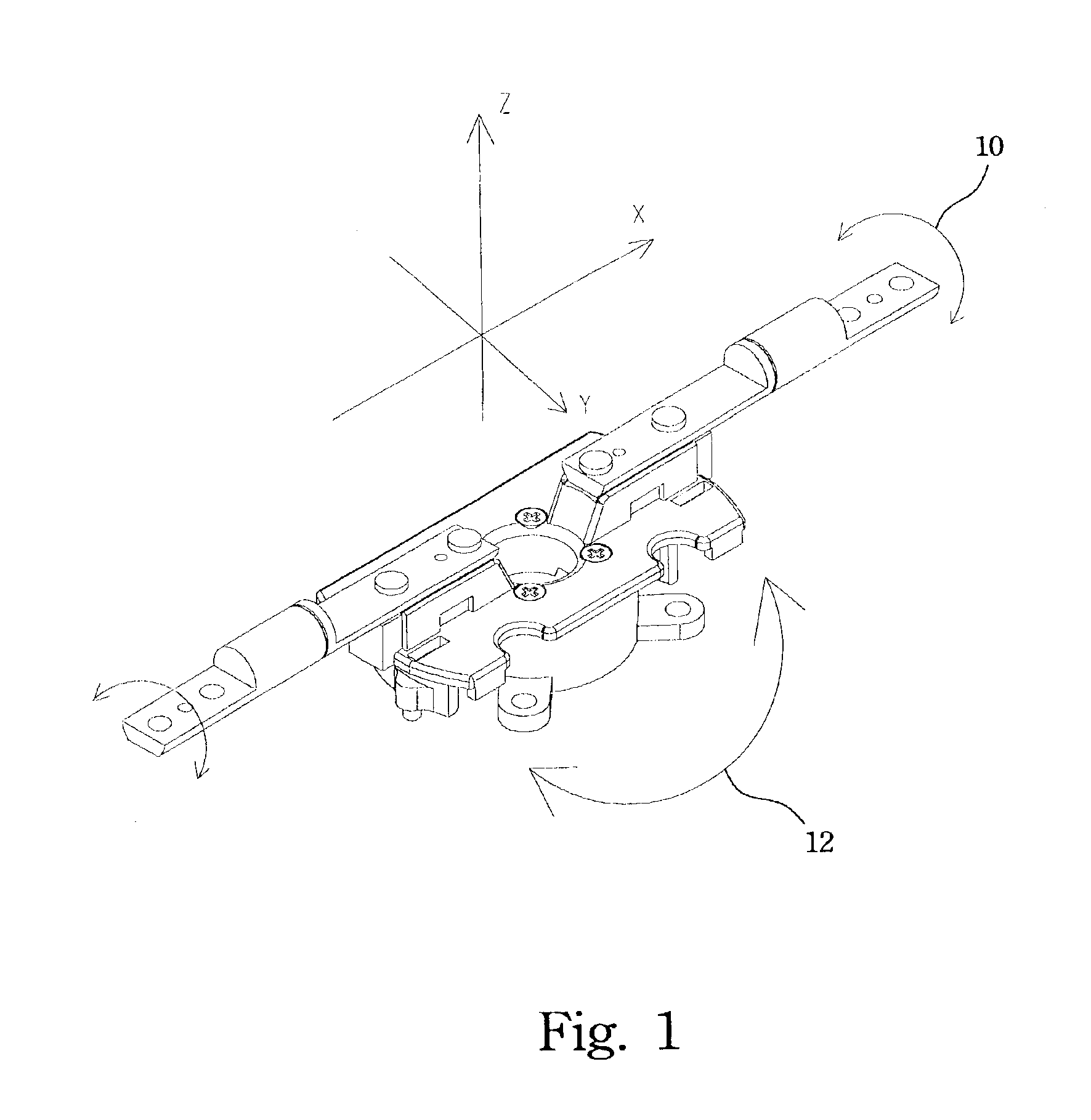
[0021]FIG. 1 illustrates a perspective view of a swivel hinge apparatus according to one preferred embodiment of this invention. The swivel hinge apparatus of the present invention has two rotational degrees of freedom. A rotation direction 10 indicates rotation around the X-axis. A LCD panel is opened and closed in the rotation direction 10. A rotation direction 12 indicates rotation around the Z-axis. A LCD panel's display view can be adjusted in the rotation direction 12. The purpose of present invention is to provide an angular fixing function. The detailed structure of the swivel hinge apparatus is described below.

[0022]FIG. 2 illustrates an exploded view of a swivel hinge apparatus according to...


PUM


Abstract

A swivel hinge with angular fixing structure is employed to connect a mainframe and a display means of a notebook computer. The swivel hinge has a fixture part, a fixture friction ring, a rotation part, a rotation friction ring, and an elastic ring. The fixture part mounted on the mainframe has a through hole in the center thereof. The fixture friction ring mounted on the fixture part has at least one holder on the surface. The rotation friction ring mounted on the rotation part has at least one slot in the surface thereof. The elastic ring is located between the fixture part and the fixture friction ring. If the slot and the holder on the friction ring fit into each other, the desired angular fixing function is provided.

Description

BACKGROUND OF THE INVENTION[0001]1. Field of Invention[0002]The present invention relates to a swivel hinge apparatus. More particularly, the present invention relates to a swivel hinge apparatus with an angular fixing structure for a notebook computer.[0003]2. Description of Related Art[0004]As optical and semiconductor manufacturing technology advances, Liquid Crystal Display (hereafter LCD) is widely used in all kinds of electronic appliances. LCD has several advantages, such as high resolution, small volume, light weight, low driving voltage, low power consumption and broad application. Thus, LCD application has become popular in portable TVs, cellular phones, camcorders, notebook personal computers (PCs), desktop PCs, projectors and other consumer electronics or computer products. LCD has become a mainstream technology in the display market.[0005]Generally speaking, an LCD is secured to an upper cover of a notebook PC. The upper cover can be opened while turning on the notebook...

Claims


Application Information

Patent Timeline
Patent Type & Authority Patents(United States)
IPC IPC(8): E05D3/00E05D11/00E05D11/08E05D3/10G06F1/16
CPCG06F1/162G06F1/1679G06F1/1681E05D3/10E05D11/087E05Y2900/606Y10T16/5472Y10S248/917Y10T16/5403Y10T16/54034Y10T16/540345E05Y2999/00
Inventor YANG, KUO-CHANGCHANG, JUNG-WENCHEN, WEN-HSIANG
Owner QUANTA COMPUTER INC
Learn More