
Ironing board

Inactive Publication Date: 2005-04-26
COUCH KENNETH J
View PDF8 Cites 41 Cited by
  • Summary
  • Abstract
  • Description
  • Claims
  • Application Information

AI Technical Summary

Benefits of technology

[0009]It is another object of the invention to provide control circuitry for an ironing board having a heating element rated at approximately 1500 watts, the board being suitable for use with existing commercially available domestic irons, whereby the combined use will not result in an overload on a standard domestic socket outlet of 15 or 20 amps (USA) or 13 amps (UK), even when used with mains supply voltages of 110 / 120 such as encountered extensively in the USA.
[0016]The invention thus provides a power load management system which prevents overload by prohibiting power supply simultaneously to the board element and the iron even when both are registering temperatures below their set temperatures, power under such circumstances being provided preferentially to the iron.
[0019]Preferably, the control circuitry includes switch means associated with the iron power-provision means to isolate the board element from receiving power unless an iron is connected to the iron power-provision means. Such isolation means is an important safety feature and prevents the possibility of a dangerous potential being created across the board and the iron especially in hospitals, schools, hotels and other such places, for example by using another iron fed from a different phase.

Problems solved by technology

A problem with ironing apparatus as described above is that there is a risk of electrical overload where the board element and iron element are both being heated simultaneously.
The problem is made worse by the increase in wattage of domestic irons in recent years, 2 kW now being commonplace in Europe, and especially when the board heating element requires sufficiently high power rating for initial fast heat-up and recovery during the thermostatic control cycle.
The problem is even more acute in countries such as the USA with lower mains voltages creating proportionally higher current demands in excess of standard domestic outlet socket ratings, this being the principal reason why combined heated ironing broads and electric irons for double sided ironing have thus far not enjoyed commercial success in the USA.

Method used


Image

  • Ironing board
  • Ironing board
  • Ironing board

Examples


Embodiment Construction

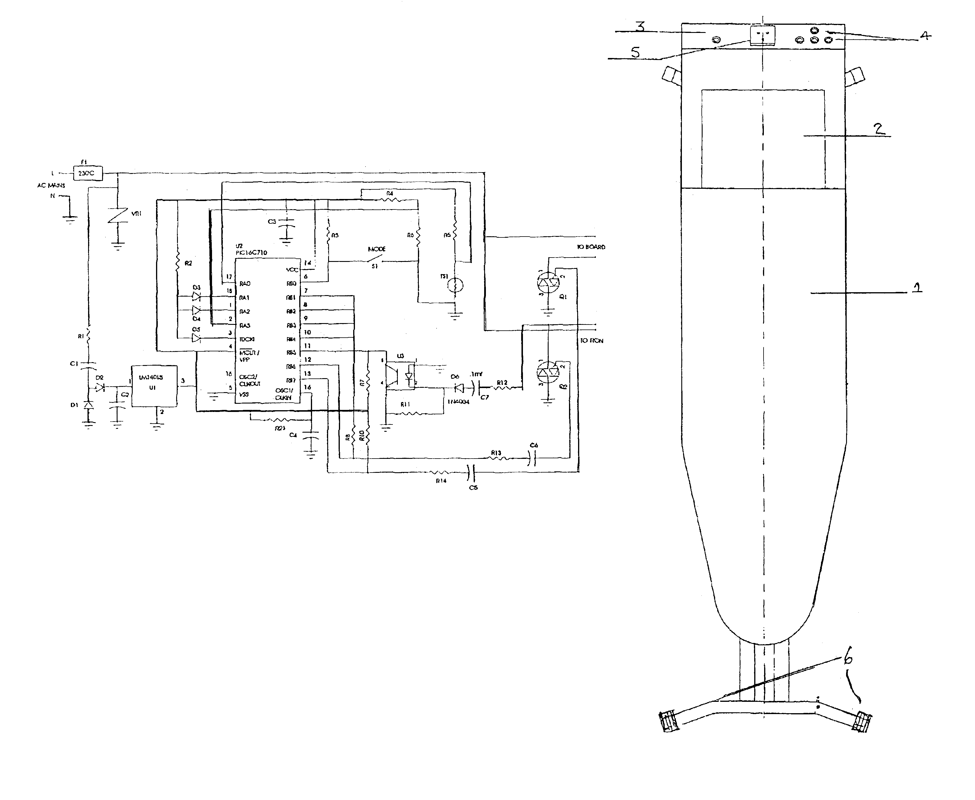
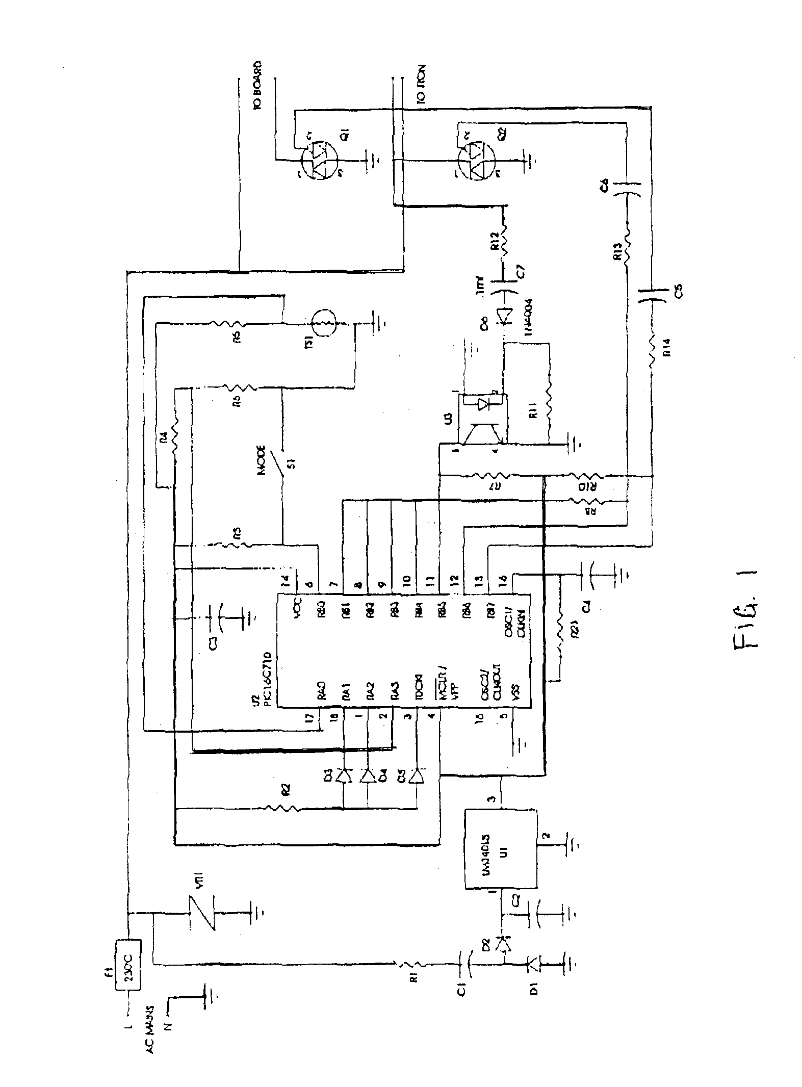
[0028]Referring firstly to FIG. 1 and, where it contains, equivalent componentry, FIG. 5, the circuit is designed to monitor the load connected to the “Iron” output, and depending on the presence of that load determines the availability of power to the “Board” output.

[0029]Additionally, the circuit provides user functions via the “mode” switch S1. There are four modes available. Mode 0 is off. This is the default mode that occurs upon the application of AC Mains, or may be entered by successive presses of the mode switch. Modes 1, 2, and 3 are all “on” functions. Different temperature settings are programmed into each of the mode 1-3 settings. Three LEDs (D3, D4 and D5) indicate the currently selected mode. Temperature sensor TS1 is located within measurement proximity of the board and is used to provide monitoring of the board temperature by the CPU (U2).

AC Mains

[0030]The circuit common is connected to the AC Mains Neutral lead. The Line or “hot” lead powers the circuit via a therm...


PUM


Abstract

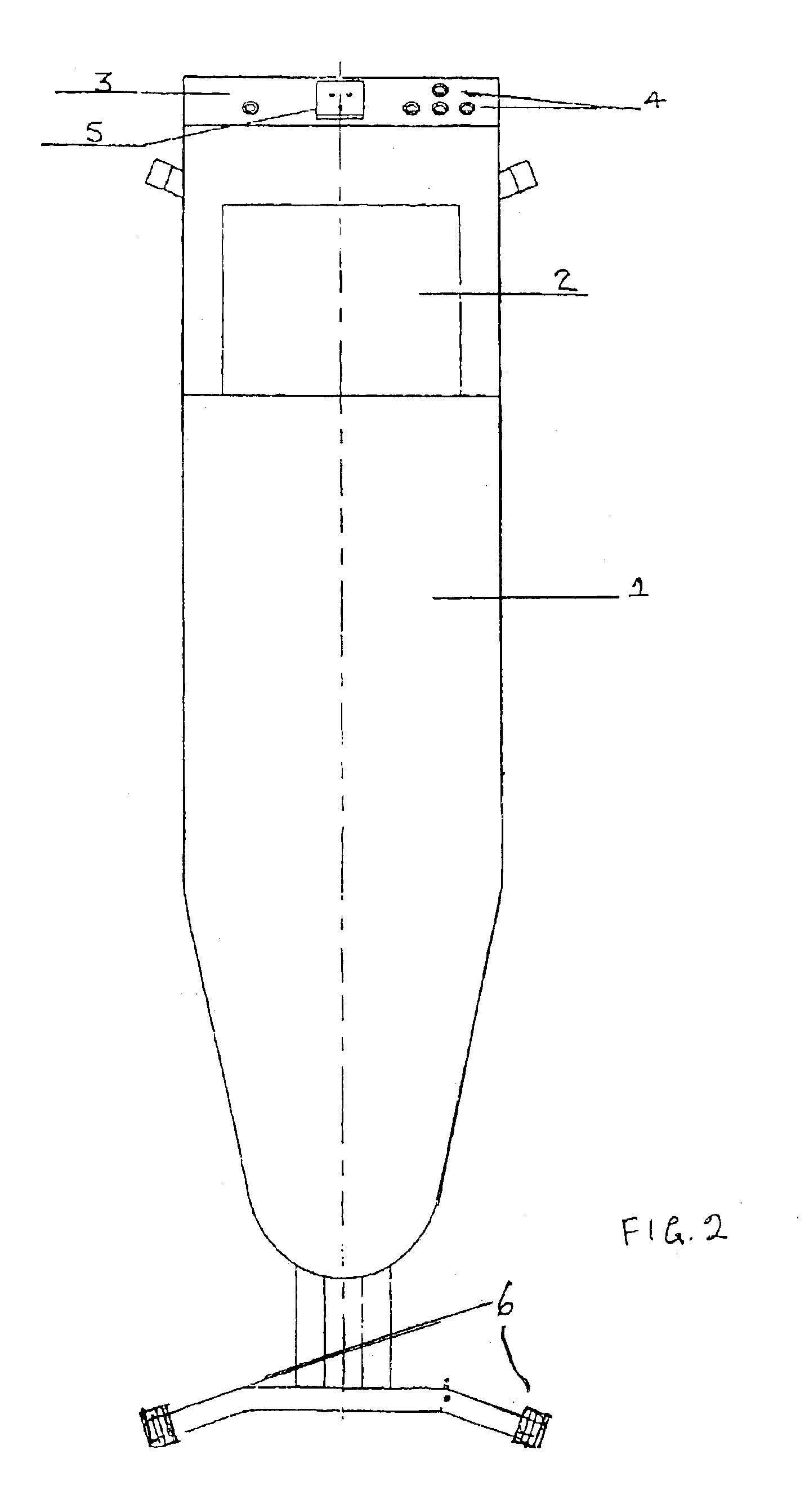
An ironing board has an electrically heated working surface with an electrical heater element disposed therein and an electrical connector for connection of an electrically heated iron. A power management system within the ironing board has a sensor that detects whether the iron is connected to the ironing board. The ironing board and iron can be selectively set to one of a plurality of heat ranges. The power management system detects thermostatically regulated demands for electrical current by each of the ironing board and iron and a controller selectively provides electrical current to at most one of the ironing board heater element and iron so as to not exceed a predetermined maximum electrical current. Control circuitry provides either a fixed or proportional temperature differential between the ironing board and the connected iron. The ironing board can include a height adjuster for selectively adjusting a height of the ironing board.

Description

CROSS-REFERENCE TO RELATED APPLICATIONS[0001]The Present Application claims the benefit under 35 U.S.C. §119(e) of provisional patent application Ser. No. 60,364,044 filed on Mar. 15, 2002, the entirety of which is hereby incorporated by reference.BACKGROUND OF THE INVENTION[0002]1. Field of the Invention[0003]This invention relates to domestic ironing boards of the type including heating elements to enable clothes to be ironed by applying heat both from the board and from the iron.[0004]2. Background Information[0005]EP-A-0126530 describes an ironing board which is heatable by means of an electrical heater element mounted in the board and controlled by a control circuit also mounted in the board, the control circuit including means for electrically connecting thereto an electrically-heated flat iron, whereby temperature control of the iron can be effected from the control circuit on the board. Preferably, the heater elements of the board and the iron are supplied from a common sour...

Claims


Application Information

Patent Timeline
IPC IPC(8): D06F81/08D06F81/00
CPCD06F81/08
Inventor COUCH, KENNETH J.SLATER, WAYNE A.
Owner COUCH KENNETH J
Learn More