Power supply structure of electromotive tool

Inactive Publication Date: 2005-04-26
LIN JACK
View PDF11 Cites 40 Cited by
  • Summary
  • Abstract
  • Description
  • Claims
  • Application Information

AI Technical Summary

Benefits of technology

[0013]Accordingly, the primary object of the present invention is to provide a power supply structure of an electromotive tool which comprises a body and a transformer. The body comprises a clamp at one end of the body; and an electromotive motor for driving the clamp to rotate; a control button installed at one lateral side of the body for controlling the electromotive motor; a battery seat being installed at another end of the body; the battery seat containing a battery and a control circuit; the control circuit having an inserting hole; an over current protection device of a charging circuit; and a switch; a transformer inserting into the inserting hole. By switching the switch of the control circuit to select an external power supply and a battery power supply. The control circuit serves for actuating the electromotive motor and charging the battery and the over current protection device serves to monitor the charging current so as to protect the battery.
[0014]Moreover, in the present invention, the control ci

Problems solved by technology

However, this is inconvenient and thus chargeable electromotive tool with batteries is design to improve the prior art defect.
When power is supplied to the prior art electromotive tool externally, the battery in the battery seat can not be charged.
Since the electromotive tool is held by one hand and thus it is heavy, the user cannot hold it easily for operation.
Thus efficiency and quality of the work are reduced.
Or the hand of the user will

Method used


Image

  • Power supply structure of electromotive tool
  • Power supply structure of electromotive tool
  • Power supply structure of electromotive tool

Examples


Embodiment Construction

[0023]In order that those skilled in the art can further understand the present invention, a description will be described in the following in details. However, these descriptions and the appended drawings are only used to cause those skilled in the art to understand the objects, features, and characteristics of the present invention, but not to be used to confine the scope and spirit of the present invention defined in the appended claims.

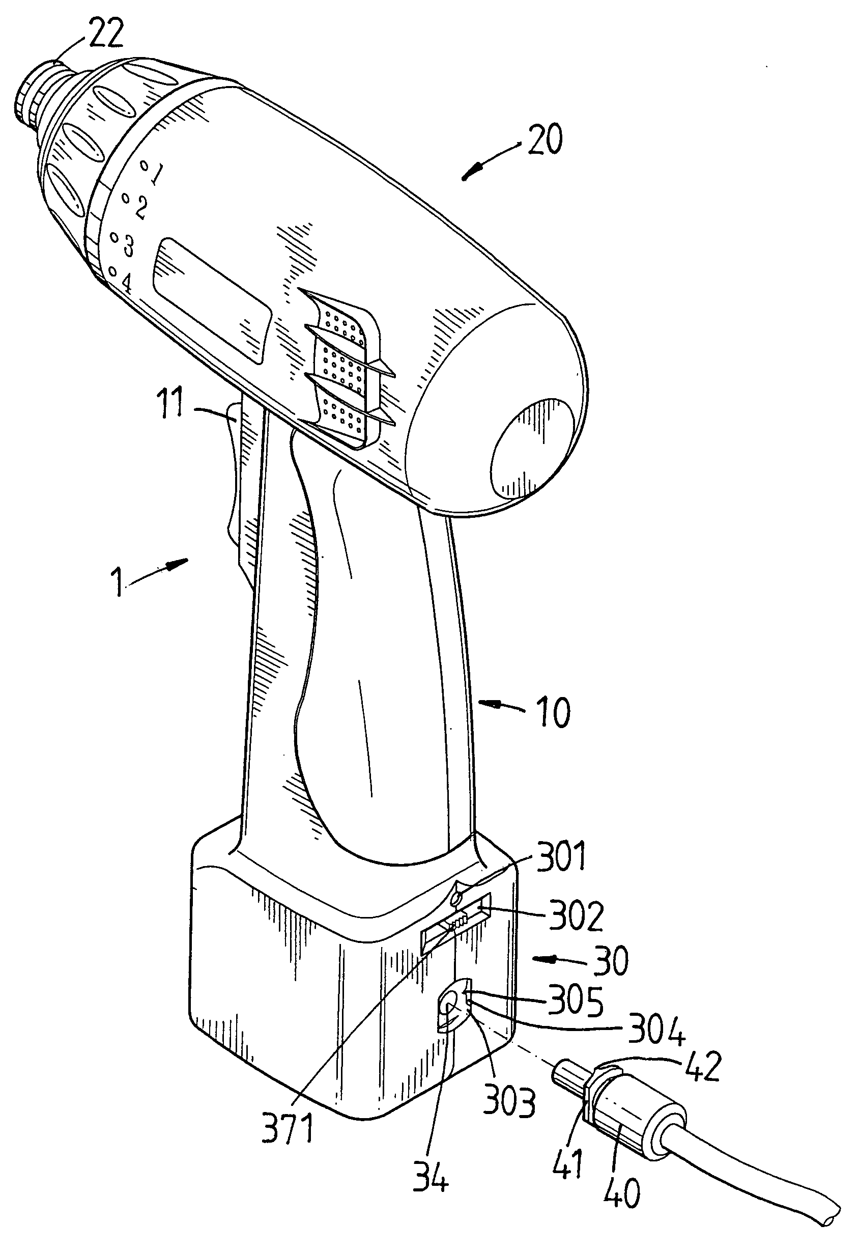
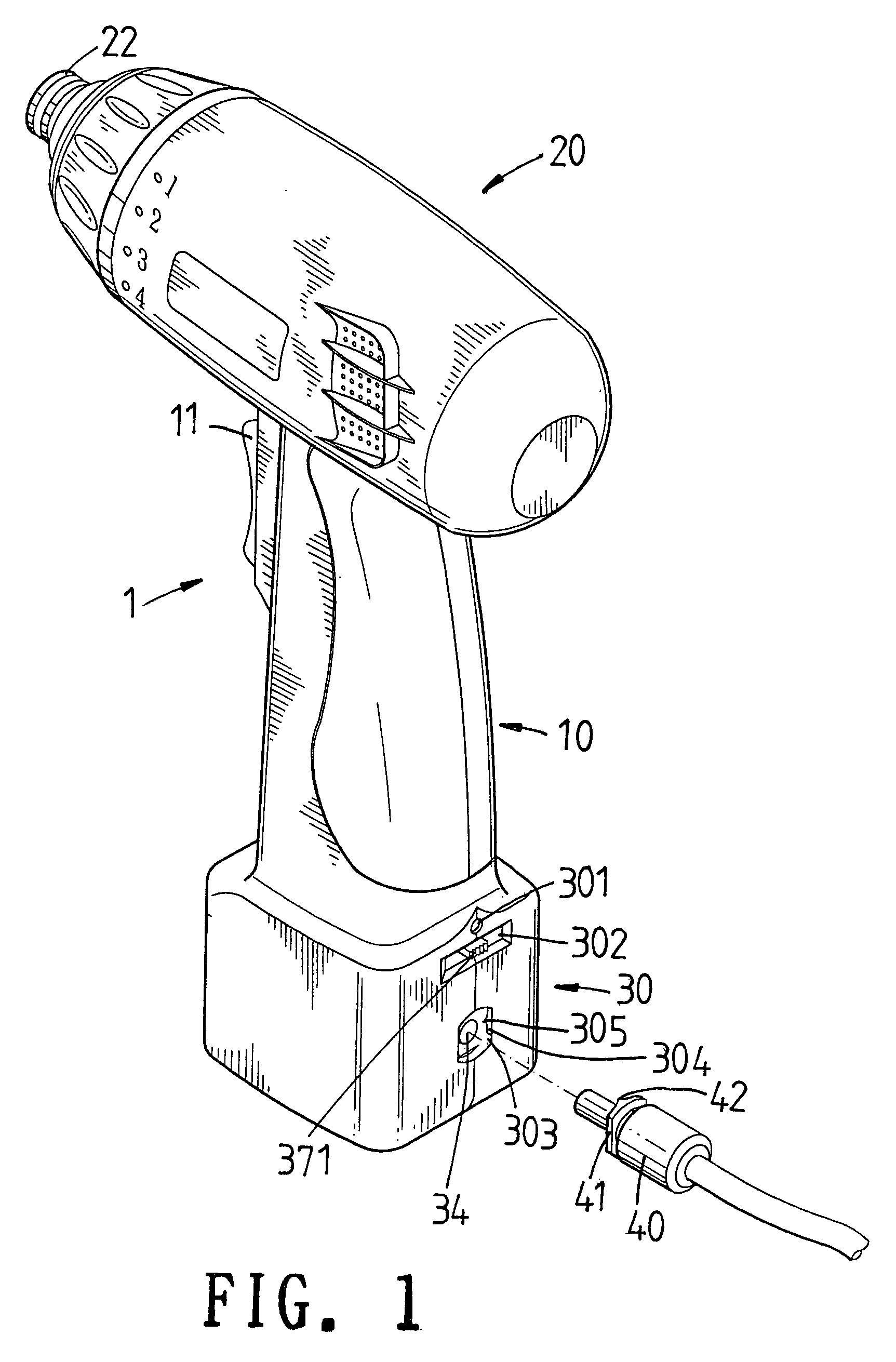
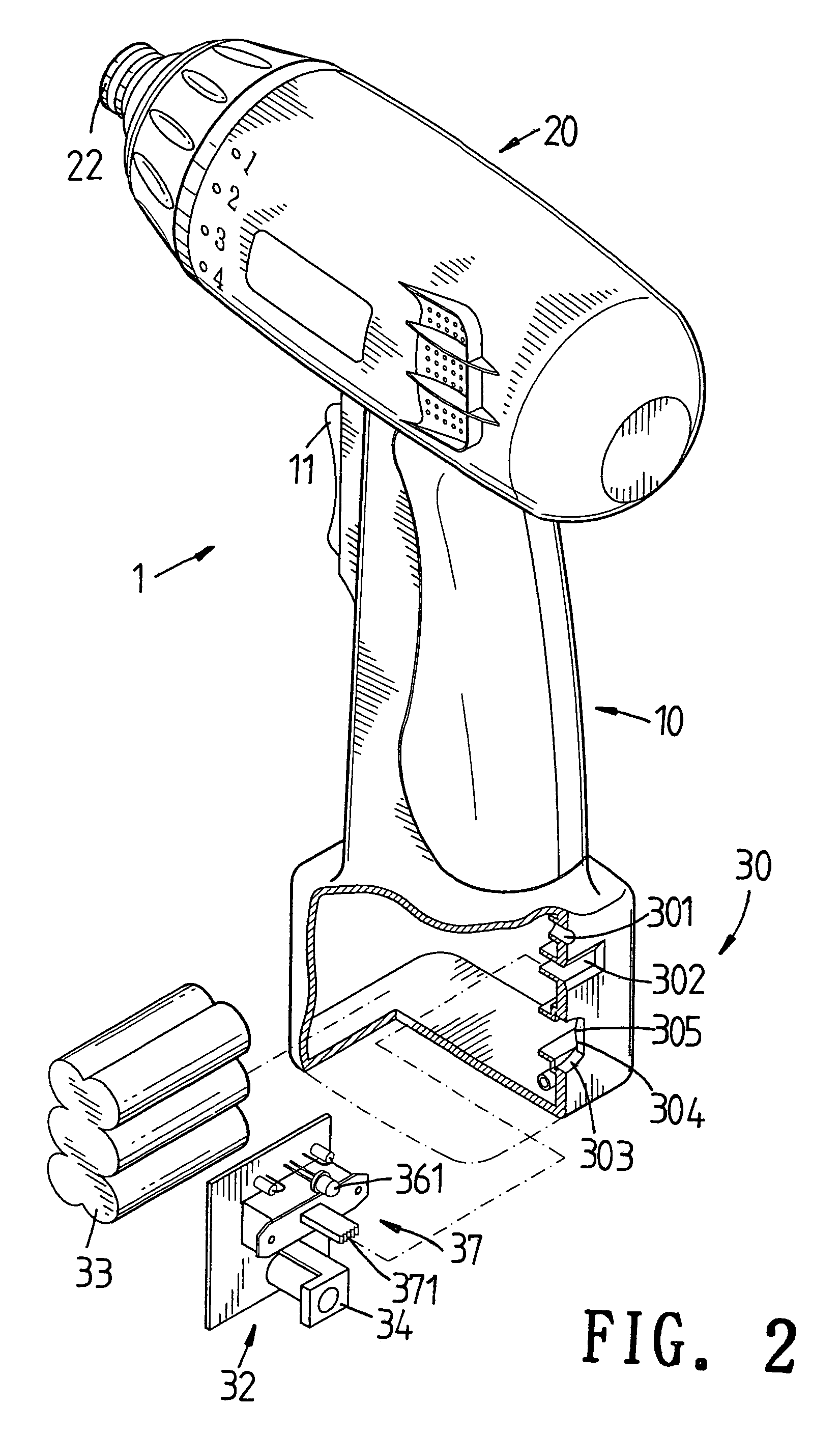
[0024]Referring to FIGS. 1 to 4, the power supply structure of an electromotive tool of the present invention is illustrated. The electromotive tool 1 includes a body and a transformer. The body has a holding portion 10. A top of the holding portion 10 is transversally installed with an acting portion 20 and has a battery seat 30 at a bottom side of the holding portion 10.

[0025]The acting portion 20 is a hollow casing having a predetermined shape. An electromotive motor (not shown) is firmly secured to an interior of the casing. The electromotive...


PUM

PropertyMeasurementUnit
Angleaaaaaaaaaa
Poweraaaaaaaaaa
Currentaaaaaaaaaa

Abstract

A power supply structure of an electromotive tool comprises a body and a transformer. The body comprises a clamp at one end of the body; and an electromotive motor for driving the clamp to rotate; a control button installed at one lateral side of the body for controlling the electromotive motor; a battery seat being installed at another end of the body; the battery seat containing a battery and a control circuit; the control circuit having an inserting hole; an over current protection device of a charging circuit; and a switch; a transformer inserting into the inserting hole. By switching the switch of the control circuit to select an external power supply and a battery power supply. The control circuit serves for actuating the electromotive motor and charging the battery and the over current protection device serves to monitor the charging current so as to protect the battery.

Description

FIELD OF THE INVENTION[0001]The present invention relates to a power supply structure, and particular to an electromotive tool which can store electrical energy.BACKGROUND OF THE INVENTION[0002]The prior art electromotive tool has power supplied by connecting wire to a power supply. However, this is inconvenient and thus chargeable electromotive tool with batteries is design to improve the prior art defect.[0003]The prior art chargeable electromotive tool includes a plug-in tool and a battery seat. A top of the tool has a transversal operation portion. One end of the portion is a clamp for clamping a tool head. Another end is downward extended with a longitudinal handle. A bottom of the hollow handle has an inserting end which extends with the operation portion for assembling the battery seat.[0004]The interior of the seat body of the battery seat has a battery, a transformer, and a charging circuit. One end of the seat body is protruded with an inserting post for inserting into the...

Claims


Application Information

Patent Timeline
IPC IPC(8): B25F5/00H02J7/00
CPCB25F5/00H02J7/0068H02J2007/0039H02J7/00304
Inventor LIN, JACK
Owner LIN JACK
Why Eureka
Try Eureka