Integral nozzle cleaning system

Inactive Publication Date: 2005-04-26
NORDSON CORP
View PDF14 Cites 9 Cited by
  • Summary
  • Abstract
  • Description
  • Claims
  • Application Information

AI Technical Summary

Benefits of technology

[0008]According to the principles of the invention, the discharge passageway in a dispenser nozzle may be cleaned frequently, while minimizing idle production time required for performing the cleaning. Frequent cleaning of the discharge passageway at periodic intervals increases the product quality by minimizing the occurrence of clogs. The ability to

Problems solved by technology

The ability to rapidly clean the discharge passageway without removing the nozzle from the liquid disp

Method used


Image

  • Integral nozzle cleaning system
  • Integral nozzle cleaning system
  • Integral nozzle cleaning system

Examples


Example

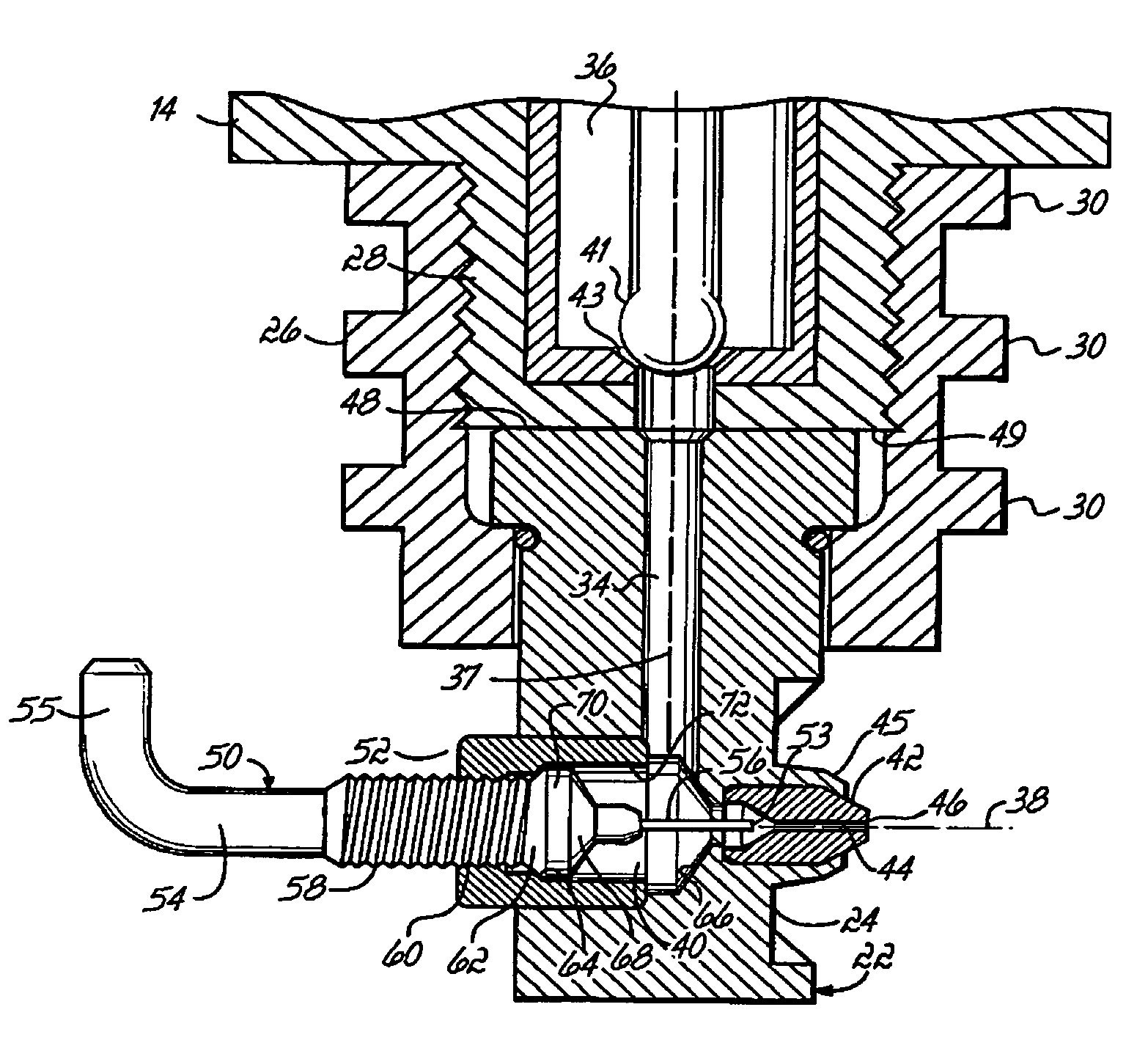
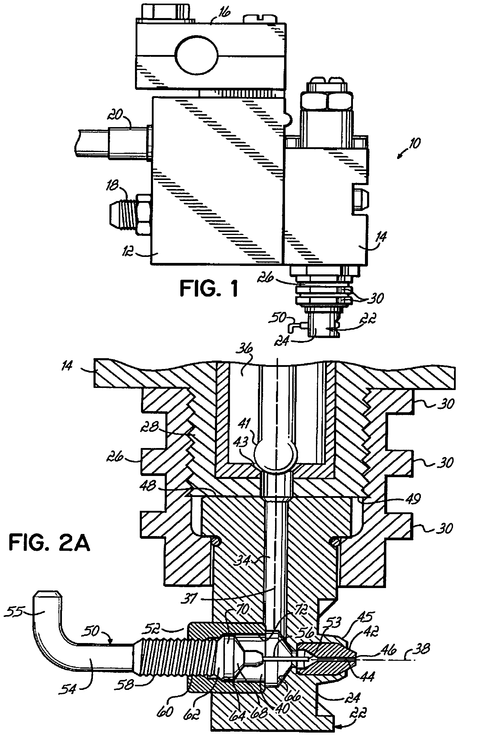
[0015]With reference to FIG. 1, a liquid dispensing system 10 for dispensing liquids, such as thermoplastic materials and hot melt adhesives, generally includes a gun body 12 and a dispenser module 14 mounted to the gun body 12. The gun body 12 is provided with a mounting bracket 16 mountable to a suitable support structure (not shown), a hose port 18 for connection of a fluid line to supply liquid, and a cord set 20 that provides electrical connections. Dispenser module 14 may be any suitable flow control device adapter receive and dispense liquid. Typically, dispenser module 14 is configured with a valve assembly that is actuated between an open position for dispensing liquid and a closed position in which the flow of liquid is discontinued. The invention contemplates that the dispenser module 14 may be any liquid distribution manifold or device that may or may not include valve assemblies and that has liquid passageways for providing liquid to one or more nozzles.

[0016]With refe...


PUM


Abstract

A nozzle for a liquid dispenser that incorporates a cleaning probe capable of removing foreign debris from a nozzle discharge passageway. The cleaning probe is moveable between a retracted position that permits fluid flow to a discharge orifice terminating the discharge passageway and an extended position in which the cleaning probe extends into the discharge passageway. As the cleaning fixture advances from the retracted position to the extended position, foreign debris present in the discharge passageway is displaced and ejected out of the discharge orifice.

Description

FIELD OF THE INVENTION[0001]The present invention generally relates to liquid dispensing apparatus and methods and, more particularly, to nozzles for liquid dispensing modules having a need to be cleaned of debris which may collect and cause clogging.BACKGROUND OF THE INVENTION[0002]Liquid dispensing systems are incorporated into many manufacturing production lines for dispensing a liquid onto a substrate. Certain liquid dispensing systems are configured for applying a pattern of a heated liquid, such as a thermoplastic material or a hot melt adhesive, to a continuously-moving substrate, such as a woven or non-woven web used in the manufacture of multilayer diapers and other multilayer hygienic products. To that end, liquid dispensing systems include one or more discharge passageways arranged to provide the pattern. Typically, the discharge passageways are located in corresponding nozzles removably attached directly or indirectly to a liquid distribution manifold. The flow of liquid...

Claims


Application Information

Patent Timeline
IPC IPC(8): B05B15/02B05C5/02
CPCB05B15/0233B05C5/0225B05B15/5225
Inventor GANZER, CHARLES P.
Owner NORDSON CORP
Why Eureka
Try Eureka